


Activity diagrams can be used in many stages of software development because they make system behavior easier to discuss. Since they are visually familiar to anyone who has used flowcharts, they are often easier to adopt than other UML diagram types.
An activity diagram helps you visualize how actions, decisions, and parallel tasks move through a system or business process. Teams use them to document workflows, clarify requirements, and spot gaps before implementation.
This tutorial covers the fundamentals you need to start drawing and reviewing activity diagrams with confidence. In this guide, you will find:
What Is an Activity Diagram?
A UML activity diagram is a behavioral diagram that shows how actions, decisions, and parallel tasks move through a system, use case, or business process. It helps teams understand what happens first, what happens next, where the flow branches, and which steps happen at the same time.
Activity diagrams are often used in software development, business analysis, and process improvement because they make complex workflows easier to explain to both technical and non-technical stakeholders. They are similar to flowcharts, but use UML-specific notation to show behavior, responsibilities, object flows, and concurrent paths more precisely.
When to use an activity diagram
Use an activity diagram when you need to show how a process moves from one step to the next, especially when that process includes decisions, parallel work, multiple actors, or handoffs between teams and systems.
Activity diagrams are especially useful for:
- Explaining the flow of a use case or user journey
- Mapping a business process before automation or redesign
- Visualizing system behavior at a high level
- Documenting responsibilities with swimlanes
- Identifying bottlenecks, unnecessary steps, and missing conditions
Activity diagram vs. flowchart
Flowcharts are useful for showing a simple sequence of steps. Activity diagrams go further by using UML notation to represent system behavior, object flows, swimlanes, decisions, and concurrent paths. If you need a diagram that fits software analysis and design work, an activity diagram is usually the better choice.
When not to use an activity diagram
Choose a simpler visual when the extra UML detail will not help the reader. A basic flowchart is often enough for a short checklist or a straightforward operational process. If you need to show system structure instead of behavior, a class diagram, component diagram, or architecture diagram will usually be a better fit.
Activity Diagram Symbols
UML has specified a set of symbols and rules for drawing activity diagrams. Following are the commonly used activity diagram symbols with explanations.
| Symbol | Name | Use |
|---|---|---|
 | Start/ Initial Node | Used to represent the starting point or the initial state of an activity |
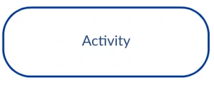 | Activity / Action State | Used to represent the activities of the process |
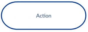 | Action | Used to represent the executable sub-areas of an activity |
 | Control Flow / Edge | Used to represent the flow of control from one action to the other |
 | Object Flow / Control Edge | Used to represent the path of objects moving through the activity |
 | Activity Final Node | Used to mark the end of all control flows within the activity |
 | Flow Final Node | Used to mark the end of a single control flow |
 | Decision Node | Used to represent a conditional branch point with one input and multiple outputs |
 | Merge Node | Used to represent the merging of flows. It has several inputs, but one output. |
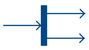 | Fork | Used to represent a flow that may branch into two or more parallel flows |
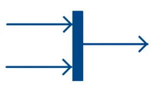 | Merge | Used to represent two inputs that merge into one output |
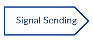 | Signal Sending | Used to represent the action of sending a signal to an accepting activity |
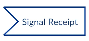 | Signal Receipt | Used to represent that the signal is received |
 | Note/ Comment | Used to add relevant comments to elements |
Activity Diagrams with Swimlanes
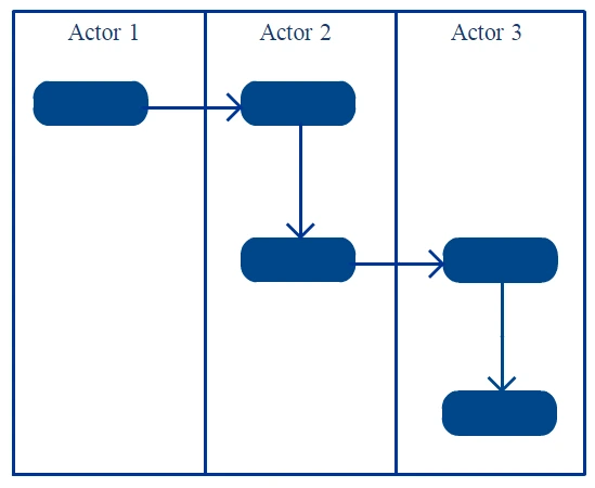
In activity diagrams, swimlanes - also known as partitions - are used to represent or group actions carried out by different actors in a single thread. Here are a few tips you can follow when using swimlanes.
- Add swimlanes to linear processes. It makes it easy to read.
- Don’t add more than 5 swimlanes.
- Arrange swimlanes in a logical manner.
Activity diagram best practices
Before you move on to drawing, keep these practical guidelines in mind:
- Start with one clear scenario instead of trying to model every possible variation in one diagram
- Use short, action-oriented labels such as “Review request” or “Approve order”
- Make decision labels explicit so readers understand why the flow branches
- Show parallel work only when the tasks truly happen at the same time
- Keep the diagram at one level of detail for the intended audience
How to Draw an Activity Diagram
Activity diagrams can be used to model business requirements, create a high-level view of a system’s functionalities, analyze use cases, and for various other purposes. In each of these cases, here’s how to draw an activity diagram from the beginning.
Step 1: Figure out the action steps from the use case
Here you need to identify the various activities and actions your business process or system is made up of.
Step 2: Identify the actors who are involved
If you already have figured out who the actors are, then it’s easier to discern each action they are responsible for.
Step 3: Find a flow among the activities
Figure out in which order the actions are processed. Mark down the conditions that have to be met in order to carry out certain processes, which actions occur at the same time, and whether you need to add any branches in the diagram. Also check whether some actions must be completed before others can begin.
Step 4: Add swimlanes
You have already figured out who is responsible for each action. Now it’s time to assign them a swimlane and group each action they are responsible for under them.
Step 5: Review the diagram for clarity
Once the first draft is complete, review it to make sure the start and end states are clear, decision branches are labeled, and the diagram does not mix several unrelated scenarios. A quick review with a teammate or stakeholder can help catch missing actions and ambiguous paths early.
In Creately’s free activity diagram tool, you can create the diagram faster by starting with an activity diagram template, using UML activity diagram shapes, adding swimlanes for responsibilities, and connecting actions, decisions, forks, joins, and final states with smart connectors. Teams can also comment, review, and edit the diagram together before exporting or sharing it.
Activity Diagram Examples
Explore these editable activity diagram examples to understand how different systems, workflows, and use cases can be modeled. Use them as a starting point, then customize the actions, decisions, swimlanes, and flows to match your own process.
How to choose the right activity diagram template for your project
Choosing the right activity diagram template for a project depends on several factors, including the complexity of the system or process being modeled, the level of detail required, and the specific goals of the project. Here are some factors to consider.
- The first step in choosing the right template is to determine the purpose of the activity diagram. Are you trying to model a business process, a software system, or a workflow?
- The complexity of the system or process being modeled is also an important factor in choosing the right template. If the system or process is simple, a basic template may be sufficient. However, if the system or process is more complex, select a more advanced or detailed template to start with.
- The audience for the activity diagram is also an important consideration. If the diagram is intended for technical stakeholders, a more detailed template may be appropriate. However, if the diagram is intended for non-technical stakeholders, a simpler template may be easier to understand.
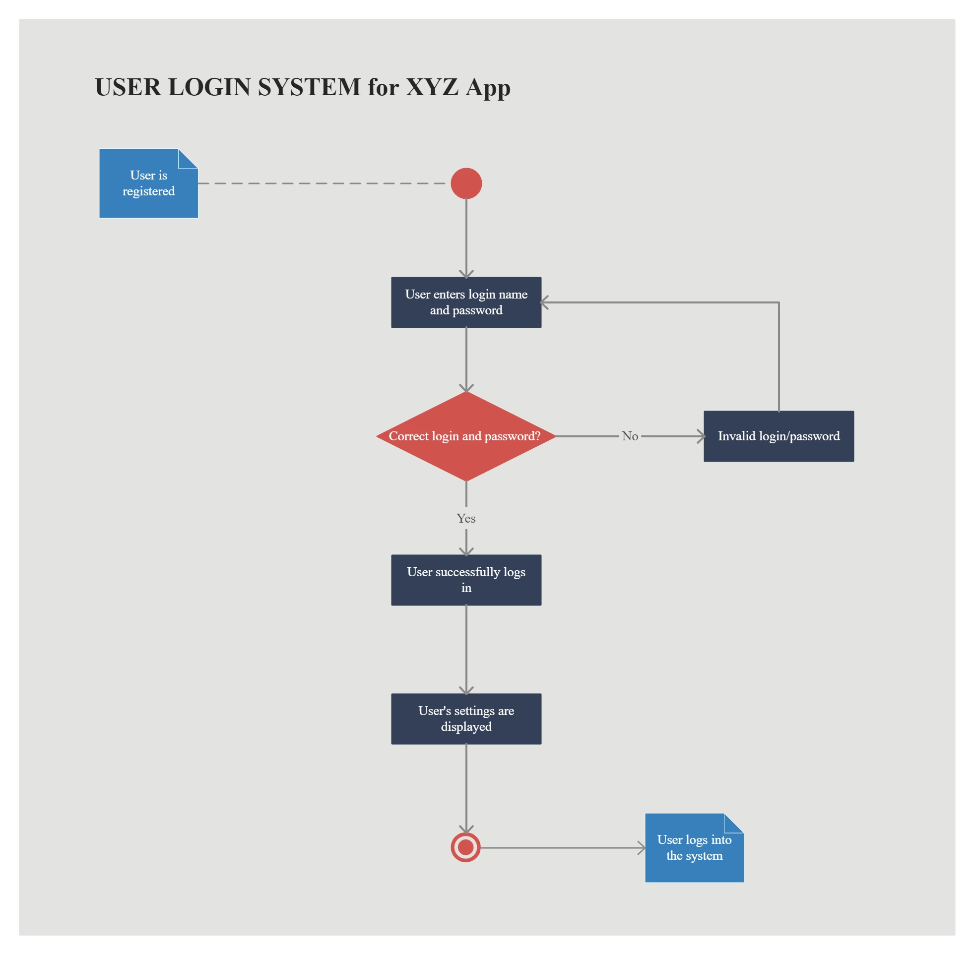
Activity Diagram for Login
Use this template to map a basic login flow, including credential entry, validation, error handling, and successful access.
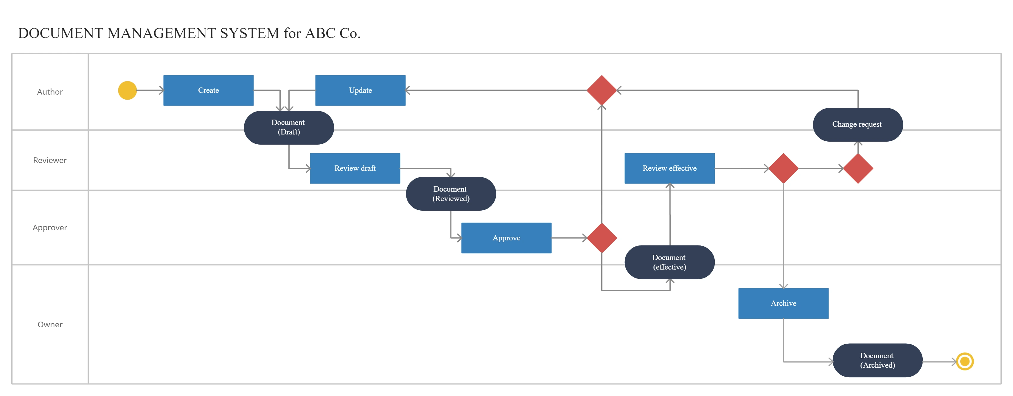
Activity Diagram for Document Management System
Use this template to show how documents move through a system, from creation and review to approval, storage, sharing, or retrieval.
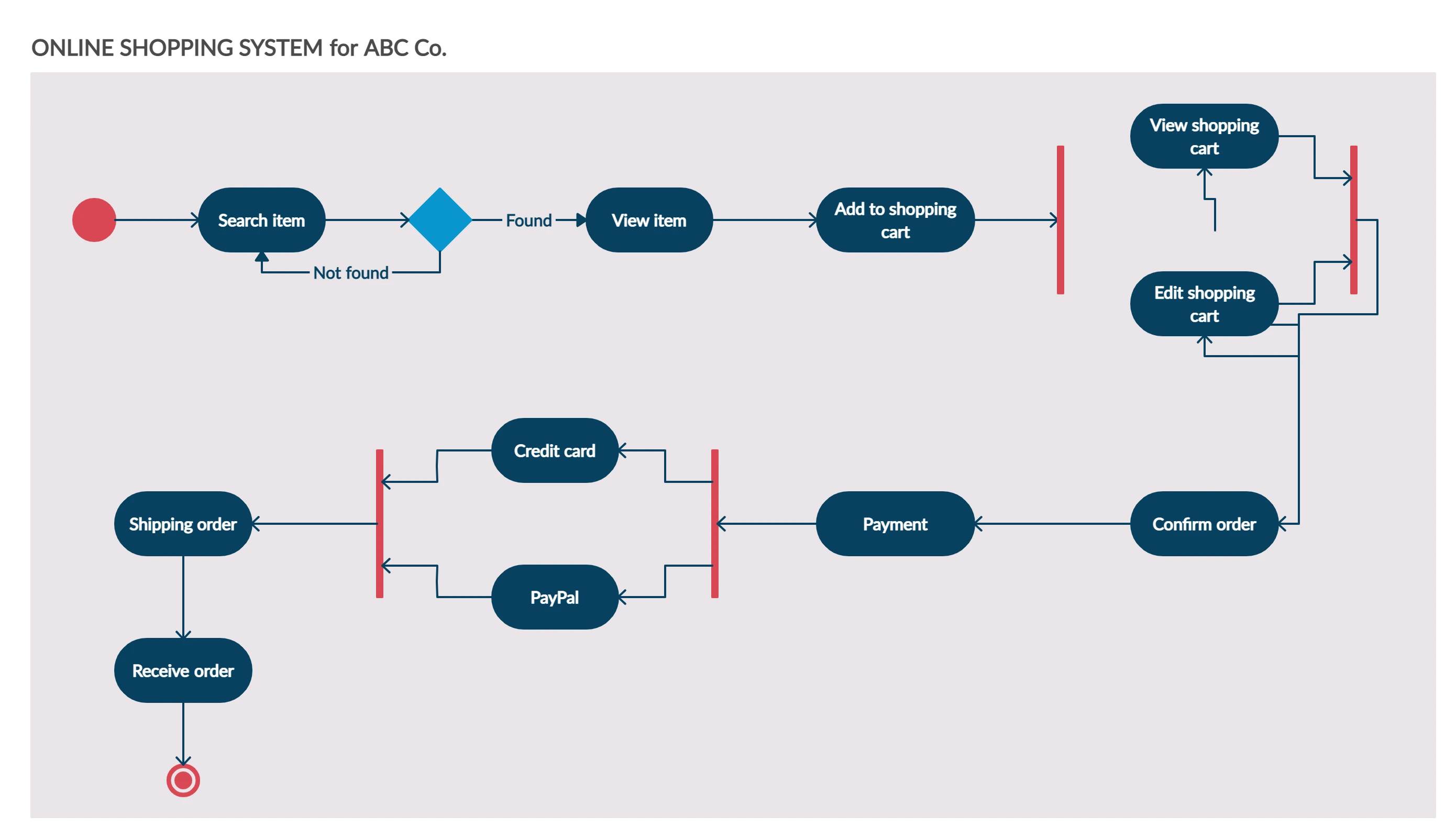
Activity Diagram for Online Shopping System
Use this template to show how a customer moves through product selection, cart review, payment, order confirmation, and possible decision points.
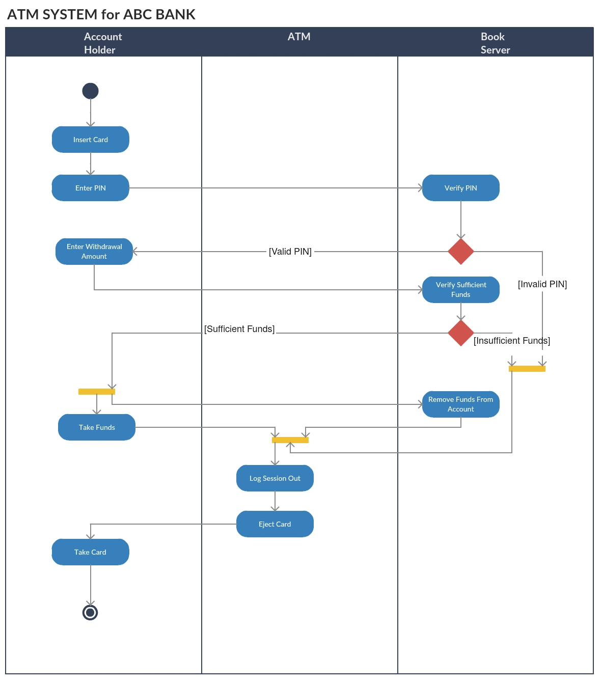
Activity Diagram for ATM
Use this template to visualize ATM actions such as card validation, PIN entry, transaction selection, cash withdrawal, balance checks, and session completion.
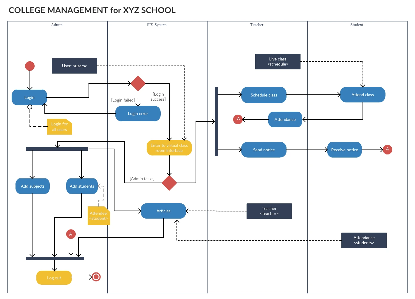
Activity Diagram for College Management System
Use this template to show how academic or administrative tasks move through a college system, such as registration, course management, approvals, and record updates.
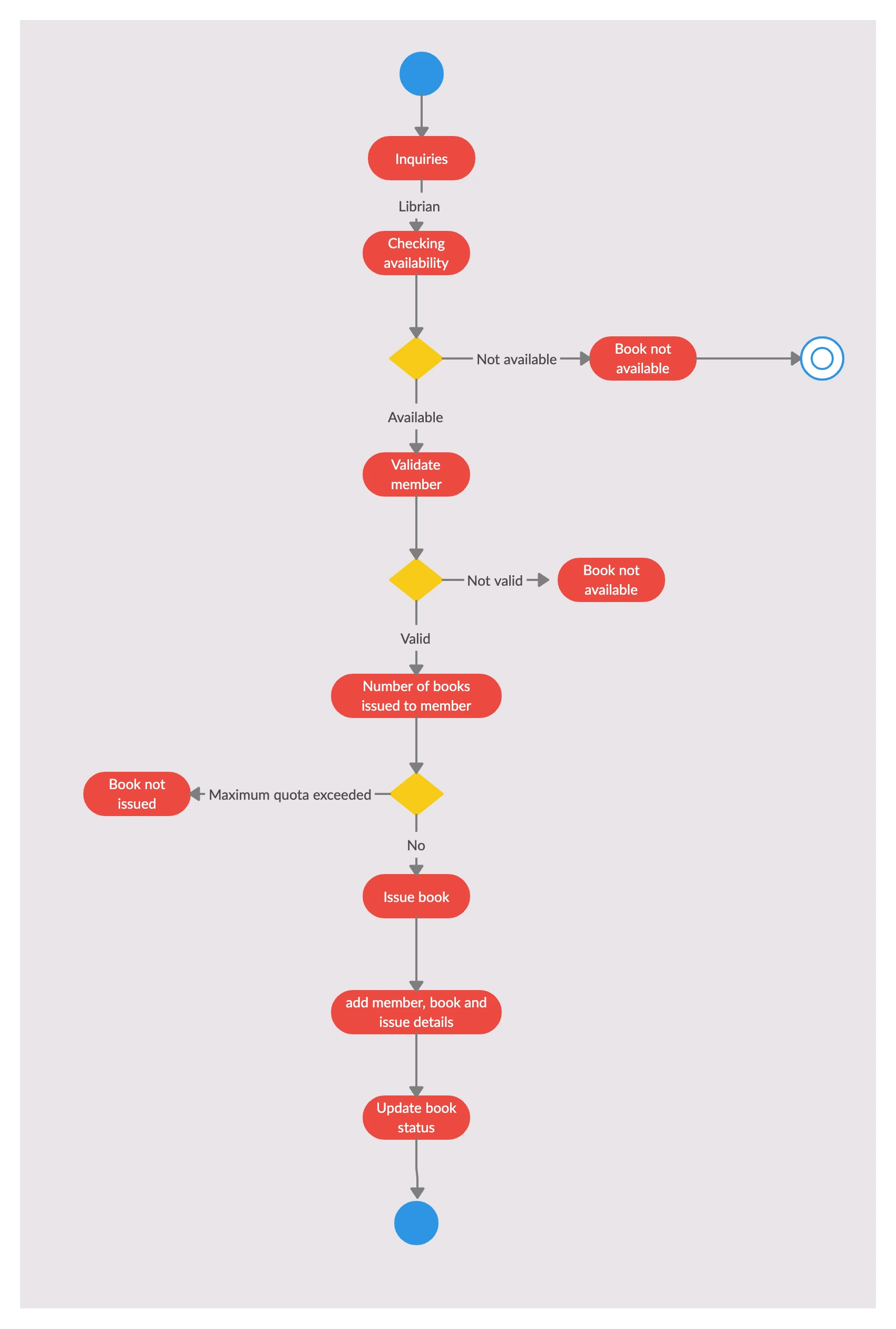
Activity Diagram for Library Management System
Use this template to visualize library workflows such as book search, borrowing, returns, renewals, fine calculation, and inventory updates.
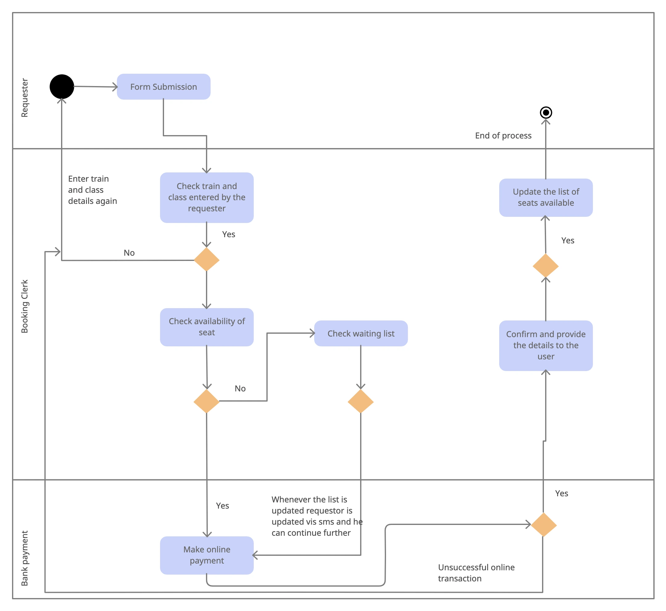
Activity Diagram for a Railway Reservation System
Use this template to map the booking flow, including train search, seat availability checks, passenger details, payment, confirmation, and cancellation paths.
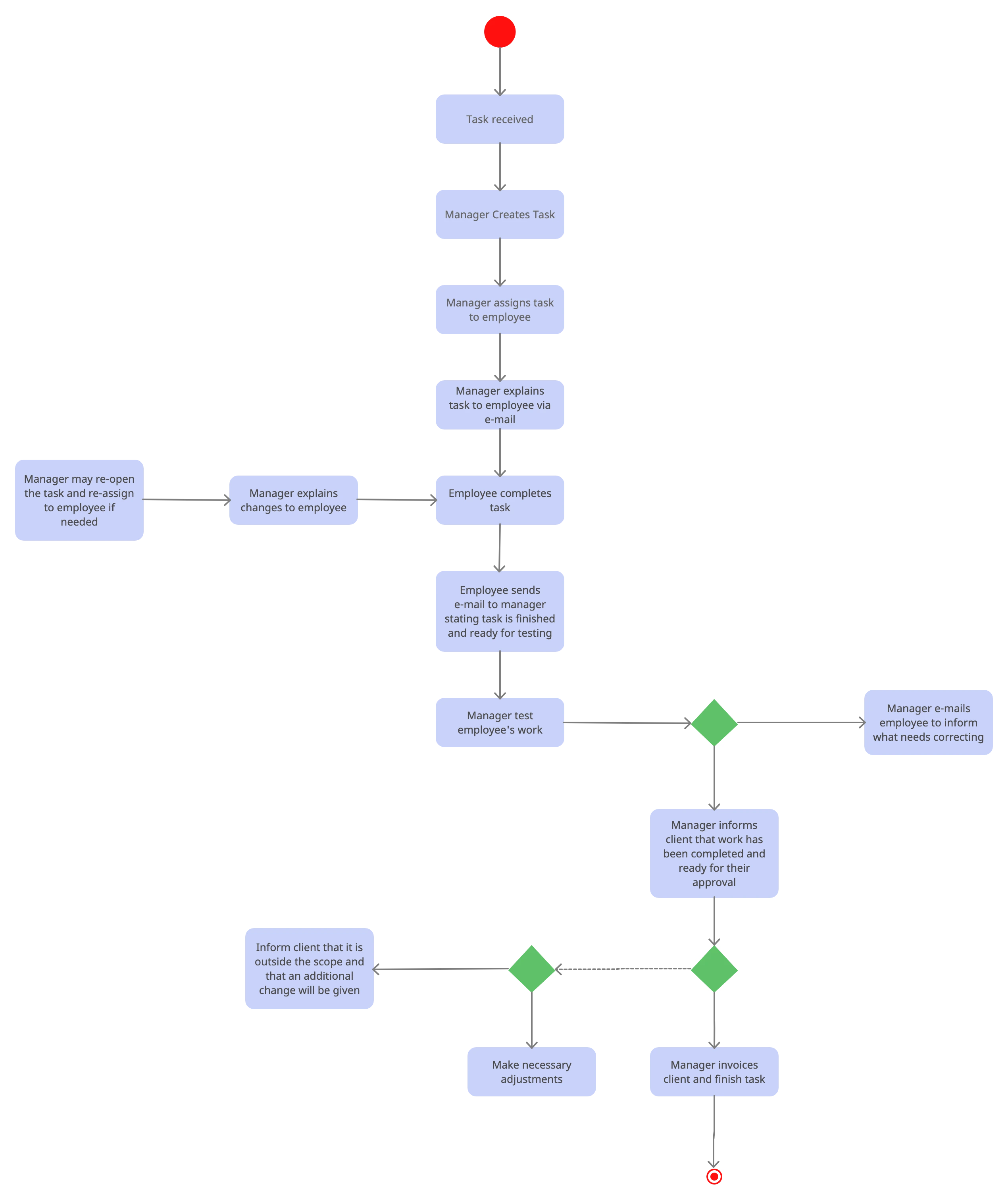
Activity Diagram for a Project Management System
Use this template to show how tasks move through a project workflow, from assignment and progress tracking to review, approval, and completion.
Common Mistakes to Avoid
Even a correct activity diagram can become hard to use if it is overloaded or inconsistent. Watch out for these common mistakes:
- Mixing multiple scenarios into one diagram
- Using vague labels such as “Process data” without explaining the action
- Forgetting guard conditions on decision branches
- Adding too many swimlanes or crossing lines that make the flow difficult to follow
- Using an activity diagram when a simpler flowchart or a different UML diagram would communicate the idea more clearly
Final Activity Diagram Review Checklist
Before you share an activity diagram with stakeholders, run through a quick quality check:
- Confirm the diagram covers one scenario or use case
- Make sure the start state, end state, and decision labels are clear
- Check that swimlanes match real responsibilities
- Remove extra branches or actions that do not support the main flow
- Ask whether a simpler diagram would communicate the same idea better
If you want to go deeper after this tutorial, compare your draft with the editable templates above and review how they handle decisions, parallel paths, and actor responsibilities. You can also explore our Easy Guide to UML Class Diagrams if you need a structure-focused UML reference next.



Ethan Brooks
How should an Activity diagram be structured for clarity and effectiveness? Would appreciate any pointers.
Amanda Athuraliya
An activity diagram should clearly show the flow of actions, decisions, and parallel tasks in a process. Start with a clear scenario, use short action-oriented labels, and add swimlanes to group responsibilities. Label decision points explicitly and keep the diagram focused on one level of detail for your audience.
Nora Mitchell
How do you usually show variable updates in a UML activity diagram during simulation? Any tips?
Amanda Athuraliya
Use actions that explicitly change the variable state, such as “Increment i” or “Set status = approved,” and connect them with control flows so the update order is clear. You can also attach notes or object flows to show how values move between actions during the simulation. In Creately, UML activity shapes, labeled connectors, and swimlanes can help separate where each variable update happens across actors or systems.
Caleb Turner
Can an action in a UML activity diagram have multiple outgoing control flows without using a decision or fork node?
Amanda Athuraliya
Yes, but the meaning depends on the modeling intent. If only one path should continue based on a condition, use a decision node with guarded outputs. If multiple paths should run in parallel after the action, use a fork node instead of drawing several direct outgoing flows from the same action. In Creately, you can add the correct UML fork or decision symbols from the activity diagram shape library and connect the branches clearly.
Maya Collins
How do you determine the correct order of actions in an activity diagram when there are branches or parallel paths? Any suggestions?
Amanda Athuraliya
Start by following the control flows from the initial node and check where the diagram branches with decision or fork nodes. A decision node means only one path continues based on a condition, while a fork means actions can happen in parallel and may not have a fixed order. If two actions are connected sequentially, the earlier one must finish before the next begins. Using swimlanes can also help you track which actor performs each step.
Liam Carter
Can one activity in a UML activity diagram have multiple outgoing arrows, or should branching always use a decision node? Any tips?
Amanda Athuraliya
Yes, an activity can have more than one outgoing flow, but the meaning matters. If the flow branches based on conditions, use a decision node with labeled guards. If multiple paths should run at the same time, use a fork node instead of drawing several arrows directly from the activity. In Creately, you can add decision and fork symbols from the UML activity diagram shape library to keep the workflow clear.
Liam Carter
How do you show multiple scheduled background jobs in an activity diagram without making the workflow confusing? Any tips?
Amanda Athuraliya
Use a fork node to show background jobs that run in parallel and label each action with the trigger or schedule, such as hourly sync or nightly cleanup. If the scheduler itself is important, model it as a separate swimlane that sends signals to the jobs. Keep the main business flow separate from recurring background tasks unless they directly affect the same process state. In Creately, you can organize these jobs with swimlanes and UML activity connectors to keep parallel paths readable.
Liam Carter
How do you show shared tasks between Admin and User swimlanes in an activity diagram? Any tips?
Amanda Athuraliya
Use separate swimlanes for the Admin and User responsibilities, then place the shared activity in the lane of the actor who performs it or in a separate system/shared services lane if both interact with it. You can connect both flows to the same action using merge and control flows, and use forks if the tasks happen concurrently. In Creately, swimlane templates and UML activity connectors make it easier to organize these parallel and shared actions clearly.
Nora Mitchell
Can an activity diagram have multiple Final Activity nodes for different end states? Any tips?
Amanda Athuraliya
Yes, an activity diagram can include multiple Activity Final nodes when different paths fully terminate the activity. Each Activity Final node ends all flows in that activity, so use them only when the entire process should stop at that point. If you only want to end one branch while other flows continue, use a Flow Final node instead.
Liam Carter
Can a decision node have more than two outgoing arrows, and can a merge node accept multiple incoming flows in an activity diagram?
Amanda Athuraliya
Yes. In UML activity diagrams, a decision node can have one incoming flow and multiple outgoing flows based on different conditions or guards. A merge node works the opposite way, allowing multiple incoming alternative flows to combine into a single outgoing flow. Just make sure each decision branch is clearly labeled so the logic stays easy to follow.
Nora Mitchell
How many output arrows can be connected to the decision node and how many input arrows can be connected to the merge node in an activity diagram? What would you recommend?
Amanda Athuraliya
Yes. A decision node can have one incoming flow and multiple outgoing flows, with each branch representing a different condition or outcome. A merge node works the opposite way by combining multiple incoming flows into a single outgoing flow. Make sure each decision branch is clearly labeled with guard conditions so the workflow stays easy to follow.
Ethan Brooks
How do you figure out the valid order of actions in an activity diagram when there are branches and parallel paths? Any tips?
Amanda Athuraliya
Start by tracing the control flow from the initial node and follow each connector through decisions, merges, forks, and joins. If you see a fork, the actions on those branches can happen in parallel, so more than one valid order may exist unless a join forces them back together before continuing. Labeling decision conditions clearly and reviewing the flow step by step on a UML activity diagram template can make possible execution paths much easier to spot.
Caleb Turner
How do you model several users working on and validating the same task in a UML activity diagram? Any suggestions?
Amanda Athuraliya
Use swimlanes to separate responsibilities by user role or team, then model the shared work with fork and join nodes to show activities happening in parallel. If multiple users can edit or validate the same item, keep the object flow connected to the shared artifact so the collaboration stays visible. In Creately, you can use UML activity diagram templates, swimlanes, and connectors to organize concurrent actions clearly without overcrowding the diagram.
Ethan Brooks
How do you represent async tasks or background threads in a UML activity diagram without splitting everything into separate diagrams?
Amanda Athuraliya
Use fork and join nodes to represent operations that run concurrently, such as connection handling and data receiving threads. Swimlanes can also help separate responsibilities between client, server, or worker threads while keeping the flow in a single diagram. If the process becomes too dense, keep one high-level activity diagram for the overall workflow and move detailed async behavior into smaller supporting diagrams.
Nora Mitchell
If there are three different actors in an activity diagram, should each actor have a swimlane or can the diagram work without swimlanes? Any suggestions?
Amanda Athuraliya
You can draw an activity diagram without swimlanes, but they are very useful when multiple actors or teams are involved because they clarify responsibility and handoffs. With three actors, creating one swimlane per actor is usually the clearest approach as long as the diagram stays readable. In Creately, you can quickly add and arrange swimlanes using the UML activity diagram shapes and connectors to keep the flow organized.
Ivy Lawson
How do action pins pass objects between actions in an activity diagram simulation? Any suggestions?
Amanda Athuraliya
Action pins represent the input or output data connected to an action. In a simulation, an output pin can hold the object created by one action and pass it through an object flow to the next action, even if the object itself is not visibly drawn inside the destination action box. The receiving action accesses that object through its input pin or object flow connection. In Creately, you can make this clearer by labeling object flows and adding notes to show what data moves between actions.
Daniel Mercer
Do expansion regions need an output collection when looping through folders and files in an activity diagram? Any suggestions?
Amanda Athuraliya
No, an expansion region does not always need an output collection. You can use it purely to iterate through a collection, and the region completes once all input elements have been processed. If you need to show actions for each folder and file separately, model the nested iterations clearly and use decision nodes inside the region for name-based conditions. In Creately, the UML activity shape library and connectors can help keep nested loops readable.
Leah Foster
How do you usually show loops and repeated actions in an activity diagram without making it confusing? Any tips?
Amanda Athuraliya
Use a decision node with a guard condition to control whether the flow repeats or exits the loop. A common pattern is: action → decision → back to the action when the condition is true, and continue forward when it is false. For collections like files or folders, you can model the repeated action clearly without needing an output collection unless the process actually produces one. In Creately, swimlanes and labeled connectors can also help keep nested loops easier to read.
Hannah Blake
How do you show a C-style continue statement inside a loop in an activity diagram? Any suggestions?
Amanda Athuraliya
Use a decision node inside the loop body and route the “continue” condition back to the loop check instead of continuing to the remaining actions in the current iteration. The normal path can proceed to the rest of the activities before returning to the loop condition. In Creately, you can model this clearly with decision diamonds, labeled control flows, and loop connectors to keep the branching easy to follow.
Ruby Sinclair
How do you handle returning to an earlier activity without duplicating the step in a UML activity diagram? Any suggestions?
Amanda Athuraliya
Use a merge node to reconnect the flow back into the earlier path instead of creating a second copy of the activity. In your example, the “no” branch from the second decision can merge into the same control flow that leads to activity C, so the process continues from there naturally. Keep the diagram focused on one scenario at a time and avoid repeating actions unless they truly represent separate states. In Creately, you can do this visually with UML activity connectors and merge symbols to keep the flow readable.