What Are Class Diagram Symbols?
UML Class Diagram symbols are the standardized notations used to represent the structure and relationships of classes in object-oriented systems. These symbols visually communicate how classes, attributes, methods, and relationships interact within a software design. They serve as a universal language for developers, analysts, and designers, helping teams model systems clearly without ambiguity.
Purpose of Class Diagram Symbols
Visualize System Structure: Represent the static framework of a system, showing how classes are organized and connected.
Clarify Object Relationships: Illustrate associations, dependencies, and inheritance among classes for easier understanding of data flow.
Define Class Details: Display key elements such as class names, attributes, and methods to describe object behavior and data storage.
Enhance Communication: Provide a common visual language that bridges developers, analysts, and stakeholders during design discussions.
Support Object-Oriented Design: Help identify encapsulation, abstraction, and hierarchy in class relationships.
Facilitate Documentation: Serve as a clear visual record of system architecture for maintenance and future development.
Improve Code Planning: Allow teams to model and validate class structures before implementation, reducing design errors.
Key Components of Class Diagram Notation
UML Class Diagram notation uses a structured visual syntax to represent classes, their attributes, operations, and relationships in a clear, standardized format. Each element follows specific rules for how it’s displayed and connected.
Class Symbol
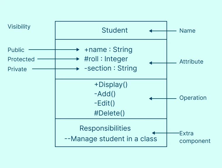
Each class groups together its attributes (data) and operations (functions) to represent its overall structure and behavior. In a Class Diagram, a class is depicted as a rectangular box divided into three sections. The top section shows the class name, the middle section lists its attributes, and the bottom section displays its operations or methods.
Class Diagram Syntax
Class Attributes: These are the data fields or properties that define a class’s state — for example, name, studentID, or grade. In a UML Class Diagram, attributes are displayed in the second section of the class box, with their data type following a colon (e.g., name: String, grade: Int). In programming terms, attributes correspond to member variables that store the object’s internal data.
Class Operations (Methods): These are the functions or actions that define what a class can do such as display(), add(), edit(), or delete(). In a UML Class Diagram, such operations are listed in the third section of the class box and represent the behaviors or services the class provides. The return type appears after a colon (e.g., add(): Boolean), and parameter types follow each parameter name (e.g., edit(studentID: Int): void). In programming, these operations correspond to methods that implement the class’s functionality and allow interaction with other objects.
Visibility: Specifies the access control for a class’s attributes and methods, determining which parts of the code can view or modify them. Visibility helps maintain encapsulation, a fundamental concept in object-oriented programming that protects internal data and behavior from unintended interference. Common visibility types include:
“+” Public – Accessible from anywhere.
“-” Private – Accessible only from within the class itself.
“#” Protected – Accessible within the class and its subclasses.
“~” Package – Accessible only within the same package or namespace.
Multiplicity and Cardinality Syntax
Specifies how many objects of one class can be linked to objects of another class. Multiplicity expresses the cardinality of relationships, describing the possible number of connected instances.
- Exactly one – 1
- Zero or one – 0..1
- Zero or Many – 0..* or *
- One or more – 1..*
Relationship Symbols
Illustrate how classes relate to or rely on each other within a system. Different types of class diagram relationships represent varying levels of connection, dependency, and responsibility between classes:
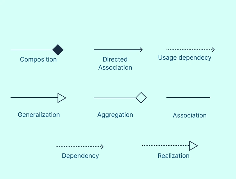
Association: A general connection between two classes is typically shown with a solid line, sometimes including arrows to indicate direction or multiplicity. It represents a basic link or interaction between objects without implying ownership or hierarchy. Example: A Teacher teaches a Course.
Aggregation: An aggregation represents a “has-a” relationship in which one class is made up of other classes, but those parts can still exist separately. It is depicted using a hollow (white) diamond on the side of the class that owns or groups the others. Example: A Library has Books and the books can exist even if the library object is deleted.
Composition: A composition is a stronger type of “has-a” relationship in which the contained parts cannot exist independently of the whole. If the whole object is destroyed, its parts are also removed. It’s shown with a filled (black) diamond on the side of the class that owns the components. Example: A House contains Rooms but if the house is deleted, the rooms cease to exist as well.
Inheritance (Generalization): An inheritance or “is-a” relationship indicates that one class derives from another, inheriting its attributes and behaviors. It’s represented by a hollow triangle pointing toward the parent (superclass). Example: A GraduateStudent inherits from a Student.
Dependency: A dependency or “uses-a” relationship indicates that one class relies on another to perform a specific task or function, usually on a temporary basis. It’s depicted with a dashed arrow pointing from the dependent class to the one it uses. Example: An OrderProcessor class depends on a PaymentGateway class to complete transactions
Realization: A realization or “implements” relationship shows that a class provides concrete behavior for an interface or abstract class it commits to. It’s represented by a dashed line with an unfilled (hollow) arrowhead pointing toward the interface or abstract class being implemented. Example: The EmailService class implements the INotificationService interface.
Navigability
Navigability indicates the direction of reference or access between two related classes in a UML diagram. It is shown using an arrow on the association line, revealing which class can locate or interact with instances of the other. Example: An arrow from Course to Instructor means each course knows who teaches it, but the instructor may not directly reference individual courses.
Class Diagram Notation and Syntax in an Example
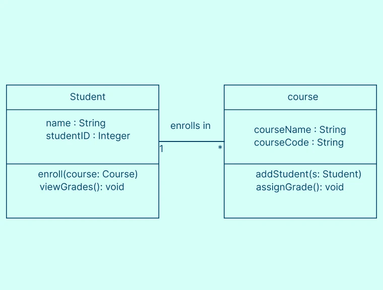
To understand how UML Class Diagram notation and syntax work in practice, let’s look at a simple example that models the relationship between two common entities: Student and Course.
Each class (e.g., Student, Course) is represented by a rectangle divided into three sections — class name, attributes, and operations.
Attributes include data fields with types (name: String, studentID: Int).
Operations define class behavior (enroll(), viewGrades()).
A solid line between the classes indicates an association relationship.
The numbers 1 and * represent multiplicity, meaning one student can enroll in multiple courses.
The arrow direction or label (e.g., enrolls in) clarifies how the relationship functions.
Best Practices for Using Class Diagram Symbols
Define a Clear Purpose: Start by identifying why you’re creating the diagram and whether it’s for system design, documentation, or communication. A focused purpose ensures the right level of detail.
Keep It Simple and Readable: Avoid clutter by limiting the number of classes in a single diagram. Break large systems into smaller, modular diagrams to maintain clarity.
Use Consistent Naming Conventions: Follow standard naming rules for classes, attributes, and operations (e.g., Student, courseName, calculateGrade()), ensuring consistency and readability.
Show Only Relevant Details: Include only the essential attributes and operations needed to understand system behavior. Skip implementation details that add unnecessary complexity.
Apply Standard UML Class Diagram Notations: Use correct UML symbols for relationships, visibility, and multiplicity to ensure diagrams are universally understandable.
Organize Layout Logically: Arrange classes to reflect their logical hierarchy or data flow. Typically it is top to bottom for inheritance and left to right for associations.
Label Relationships Clearly: Use meaningful relationship names (e.g., enrolls in, manages, belongs to) to make interactions easy to interpret.
Use Multiplicity Wisely: Always define multiplicity to specify how many instances can relate to each other, improving precision in design.
Highlight Key Associations: Emphasize important relationships like composition or aggregation when they define system structure or ownership.
Class Diagram symbols help teams interpret and design object-oriented systems more effectively by clarifying how different components are defined, connected, and interact within the model. With Creately’s Class Diagram Tool, you can easily create, customize, and connect class symbols to model your system architecture clearly in a collaborative, visual workspace.
Free Class Diagram Templates to Get Started


Browse our collection of UML Class Diagram Templates to find one that works for you.
FAQs about UML Class Diagram Symbols
Can UML Class Diagram Notation represent abstract classes and interfaces?
How do you represent static and dynamic features with UML Class Diagram symbols?
How do UML Class Diagrams connect to actual code?
Should I draw UML Class Diagrams before coding?
Resources
Boustedt, Jonas. “Students’ Different Understandings of Class Diagrams.” Computer Science Education, vol. 22, no. 1, Mar. 2012, pp. 29–62, https://doi.org/10.1080/08993408.2012.665210.
France, R, et al. “The UML as a Formal Modeling Notation.” Computer Standards & Interfaces, vol. 19, no. 7, Nov. 1998, pp. 325–334, https://doi.org/10.1016/s0920-5489(98)00020-8.