If you work in chemical, mechanical, or process engineering, chances are you’ve come across a process flow diagram (PFD). These aren’t your everyday business flowcharts—they’re high-level technical blueprints that show how materials and energy move through a system. In this guide, we’re going beyond the theory. You’ll learn how to create a process flow diagram, step by step.
If you’re new to PFDs or want a refresher on what they are and when to use them, check out our guide on what a process flow diagram is first. It covers the basics—definitions, components, and benefits.
Preparation Before You Start Drawing a PFD
Before diving into the PFD diagram, take time to plan. A solid foundation makes the rest of the process smoother and more accurate.
1. Define the scope: Clarify what part of the process you’re showing—entire plant, a single line, or a specific stage. Set clear start and end points.
2. Gather process data: Collect key details like equipment specs, flow rates, temperatures, and pressures. Use simulation results or lab data if available.
3. Review supporting docs: Check existing material balances, datasheets, and P&IDs for reliable references.
4. List major components: Identify the main units—reactors, pumps, exchangers, tanks—that need to appear in the diagram.
How to Create a PFD Step-by-Step
Here’s how to go from a blank canvas to a complete, professional PFD—one step at a time.
Step 1: Set the layout direction
Start with a basic sketch that defines the process flow across the diagram. Most PFDs follow a left-to-right layout to make reading and tracing streams easier.
Use a consistent flow direction (usually left to right)
Group process sections logically: feed, reaction, separation, recycle
Lay out major systems before drawing lines
Creately’s snap“‘to“‘grid and alignment guides help you keep this backbone straight without fiddling with manual spacing.
Step 2: Place the major equipment
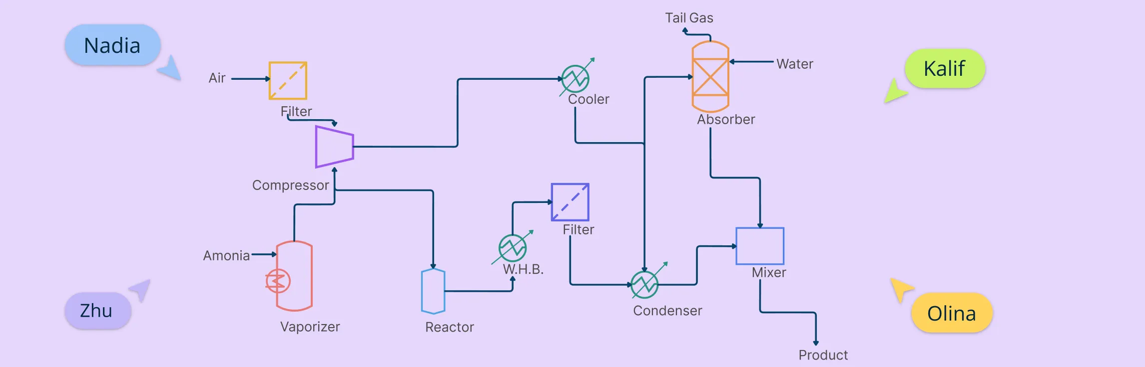
Drop in the core units—reactors, columns, heat exchangers, pumps, tanks—using symbols recognised by ISO 10628 and ISA. Label each item immediately (R‑101, E‑201, P‑301, etc.) so references stay consistent when you add lines later. A tidy rule of thumb is one alphabetic prefix per equipment type and a three‑digit series that matches the plant area. Creately’s chemical‑engineering stencil gives you these standard shapes out of the box, so you can focus on layout rather than artwork
Step 3: Connect the equipment with process lines
Draw solid lines to show the primary flow of materials. These should match the real flow direction and follow a logical path.
- Use solid lines for process streams, dashed/dotted for utilities
- Add arrowheads to indicate flow direction
- Number each stream in order (e.g., 1, 2, 3…)
- Minimize line crossings—adjust equipment positions if needed
Creately’s smart connectors stay attached when you rearrange units, saving re“‘work.
Step 4: Add key control elements (only what matters)
A high“‘level PFD usually shows just the instruments that define how the plant is steered—main control valves, flow indicators, critical temperature or pressure sensors. Place them where operators expect to see them, but resist the urge to crowd every gauge onto the sheet; the details belong in the P&ID.
Creately lets you keep these symbols on a separate layer so you can toggle them on for design reviews and off for training hand“‘outs.
Step 5: Annotate with essential operating data
Provide the minimum process data required to understand system conditions.
- Add typical temperature, pressure, and flow rate near streams
- Include composition info if relevant (e.g., for reactor feeds)
- Keep it clean—excess data belongs in a separate stream table
- Use consistent units and formatting
Step 6: Finish with labels, title block, and legend
Give your drawing a clear title, author, revision number, date, and scale. Add a small legend that explains any non“‘standard symbols or line styles; ISO 10628 expects that reference on the same sheet or immediately adjacent.
In Creately you can drag a title‑block template onto the canvas, populate the fields once, and let version‑history track future edits automatically.
Step 7: Review and validate
Walk through the diagram line by line. Does every stream have a source and a destination? Do the units sit in the right order? Cross‑check the equipment IDs against datasheets and the stream numbers against your mass‑balance spreadsheet or simulation model.
Finally, share the diagram with a colleague; Creately’s real‑time comments make questions and fixes easy to capture before the drawing is frozen.
Know Your PFD Symbols and Standards
Before you start drawing, it’s important to get familiar with the PFD symbols and conventions used in process flow diagrams.
1. Use the right symbols: Process flow diagrams rely on standard symbols to represent equipment like pumps, heat exchangers, reactors, vessels, and compressors. Depending on your industry or company, you might follow ISA, ISO, or internal standards.
2. Understand line types: Lines in a PFD aren’t just arrows—they show how materials move. Solid lines usually represent process flow, while dashed or dotted lines can indicate pneumatic, hydraulic, or auxiliary systems. Be consistent with line styles so readers can instantly recognize what’s happening.
3. Label everything clearly: Each piece of equipment should have a unique ID (like P-101 for a pump or R-202 for a reactor). Tag numbers, units, and stream labels help others understand the flow and operating conditions at a glance.
4. Include a legend: If you’re using custom symbols or specific line styles, add a simple legend off to the side.
Best Practices When Drawing PFDs
Keep it high-level - A PFD should show the big picture. Skip detailed piping, wiring, and instrumentation—that’s what the P&ID is for.
Group related equipment - Arrange units by process sections (e.g., feed prep, reaction, separation) to make the flow easy to follow.
Use layers or sections for complex systems - If the diagram gets crowded, split it into logical parts or use layers to manage visibility.
Focus on clarity over detail - Avoid cramming every data point into the diagram. Label what’s essential and keep it readable.
Why Use Creately for PFD drawing
1. Use dedicated engineering symbol libraries: Design accurate PFDs faster with ready-made, industry-standard symbols for all major equipment and components—no need to create shapes from scratch.
2.Keep connections clean with smart connectors: Easily link equipment using connectors that auto-adjust and stay attached when you move shapes.
3. Manage complexity with layers: Organize control systems, utility lines, or alternate paths on separate layers. Toggle them on/off to simplify the view or focus on specific parts.
4. Add context with integrated notes: Attach detailed notes, datasheets, or explanations to any shape or stream. Ideal for design reviews or documenting assumptions directly in the diagram.
5. Present your diagram clearly: Use presentation mode to walk through your PFD section by section—great for team meetings, stakeholder reviews, or training sessions.
6. Collaborate in real time: Invite others to co-edit the diagram live. Use in-app comments to leave feedback or ask questions without switching tools.
7. Export or share effortlessly: Download your PFD as a PDF, PNG, or SVG. Or simply share a link for others to view or comment—no extra software required. You can also embed them in any site or intranet using a secure embed code or integrations for Confluence, Slack, etc.
Get Started with Free Templates for Process Flow Diagrams
Now that you know how to create a process flow diagram, use these templates to get a head start.
Process flow diagram of ethanol production


Refinery Process Flow Diagram

Process flow diagram chemical engineering

LNG process flow diagram

ETP process flow diagram

References
www.sciencedirect.com. (n.d.). Process Flow Diagram - an overview | ScienceDirect Topics. [online] Available at: https://www.sciencedirect.com/topics/engineering/process-flow-diagram.
Nikos Filipu (2019). The Process Flow Diagram as an Aid in Academic Writing. International Conference celebrating the 65th birthday of Professor Todor Shopov entitled ‘The Pedagogy of Good Opportunities for Education for all’ held on 22 November 2017. [online] Available at: https://www.researchgate.net/publication/333339834.