Logic gates are tiny electronic devices that take one or more input signals and produce a single output based on logical rules such as AND, OR, and NOT. By combining these gates in different ways, engineers can design everything from simple calculators to complex processors that power modern computers. In this guide, we’ll explore the different logic gate types, the symbols that represent them in logic gate diagrams, and the ways they can be combined to form more complex integrated circuits.
Logic Gate Types and Symbols Used in Diagrams
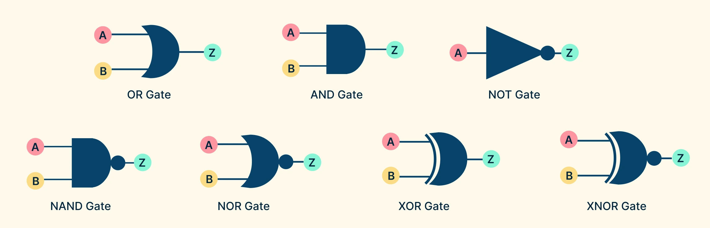
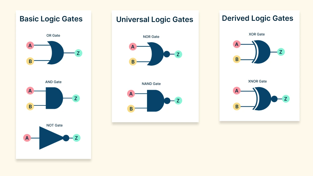
Logic gates are generally grouped into three main categories: basic gates, universal gates, and derived (advanced) gates.
Basic Logic Gates
Basic logic gates are the foundation of digital logic. They define how binary inputs (0s and 1s) are combined to produce a single binary output. The three fundamental gates are the AND gate, OR gate, and NOT gate.
Universal Logic Gates
Universal logic gates are called ‘universal’ because they can be combined to build any other type of gate, including AND, OR, and NOT. This makes them highly versatile and essential in designing efficient digital systems. The two universal gates are NAND and NOR.
Derived Logic Gates
Derived logic gates (also called complex gates or special-purpose gates) are built by combining basic or universal gates. They handle more advanced logical operations and are especially useful in circuits that require decision-making, comparison, or arithmetic functions. The NOR gate and the XNOR (Exclusive NOR) gate are derived logic gates.
To get an idea for their functions, both the standard logic gate symbols and truth tables are provided below.
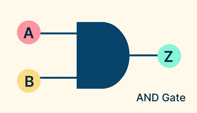
AND Gate
The AND gate performs a logical multiplication. It outputs 1 (true) only if all its inputs are 1; otherwise, the output is 0. This makes it useful for enforcing multiple conditions at once. Think of it like two switches connected in series, where electricity (output) flows only when both switches are ON (1).
AND Gate Symbol: D-shaped figure with two or more input lines entering from the left and one output line leaving from the right.
AND Gate Truth Table Boolean Equation: Y = A ⋅ B | ||
Input A | Input B | Output Y |
0 | 0 | 0 |
0 | 1 | 0 |
1 | 0 | 0 |
1 | 1 | 1 |
Real-world example: A digital lock that opens only when the correct PIN and a fingerprint scan are provided.
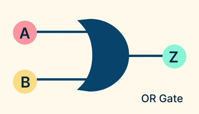
OR Gate
The OR gate performs a logical addition. It outputs 1 (true) if at least one input is 1. The output is 0 only when all inputs are 0. Think of it like two switches connected in parallel, where the light turns ON if either switch (or both) is ON.
OR Gate Symbol: A curved shape ending in a point, with input lines on the left and a single output on the right.
OR Gate Truth Table Boolean Equation: Y = A + B | ||
Input A | Input B | Output Y |
0 | 0 | 0 |
0 | 1 | 1 |
1 | 0 | 1 |
1 | 1 | 1 |
Real-world example: An emergency alarm that activates if any one of multiple buttons is pressed.
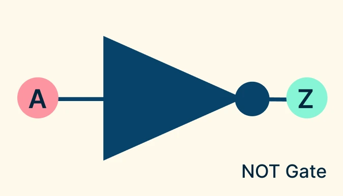
NOT Gate (Inverter)
The NOT gate reverses its input. If the input is 1, the output is 0; if the input is 0, the output is 1. Picture it as a switch wired in reverse — when the input says ON, the output forces it OFF, and vice versa.
NOT Gate Symbol: A triangle pointing right with a small circle (inversion bubble) at the output side.
NOT Gate Truth Table Boolean Equation: Y = A¯ or ¬A or A′ | |
Input | Output Y |
0 | 1 |
1 | 0 |
Real-world example: A motion sensor system where a signal is sent only when no motion is detected (the input is inverted).
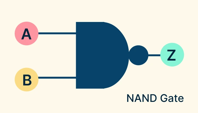
NAND Gate
The NAND gate is the opposite of the AND gate. It outputs 0 (false) only when all inputs are 1; for all other input combinations, the output is 1. It acts like an AND gate followed by a NOT, meaning it only blocks the output when every condition is active.
NAND Gate Symbol: D-shape (AND gate shape) with a small circle (NOT bubble) added at the output.
NAND Gate Truth Table Boolean Equation: Y = (A ⋅ B)¯ | ||
Input A | Input B | Output Y |
0 | 0 | 1 |
0 | 1 | 1 |
1 | 0 | 1 |
1 | 1 | 0 |
Real-world examples:
- Used in processor design because NAND alone can replicate all other gates.
- Common in memory chips (SRAM, DRAM), where NAND-based circuits store data efficiently.
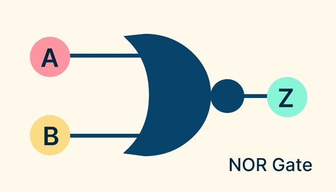
NOR Gate
The NOR gate is the opposite of the OR gate. It outputs 1 (true) only when all inputs are 0; for all other input combinations, the output is 0. Think of it as an OR gate followed by a NOT, where the system stays active only when no signals are present.
NOR Gate Symbol: Curved shape (OR gate shape) with a small circle (NOT bubble) at the output.
NOR Truth Table Boolean Equation: Y = (A + B)¯ | ||
Input A | Input B | Output Y |
0 | 0 | 1 |
0 | 1 | 0 |
1 | 0 | 0 |
1 | 1 | 0 |
Real-world examples:
- Used in control systems, where an action should only occur when no signals are present.
- Found in alarm reset circuits, ensuring the output stays inactive until all inputs return to 0.
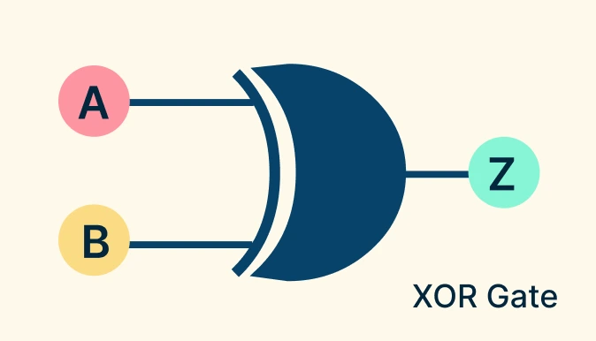
XOR (Exclusive OR) Gate
The XOR gate produces an output of 1 (true) only when the inputs are different. If both inputs are the same, the output is 0. Imagine a lamp that turns ON if exactly one button is pressed, but stays OFF if both buttons are pressed or neither is pressed.
XOR Gate Symbol: Curved shape (OR gate shape) with an extra curved line at the input side.
XOR Gate Truth Table Boolean Equation: Y = A ⊕ B or, Y = (A · B¯) + (A¯ · B) | ||
Input A | Input B | Output Y |
0 | 0 | 0 |
0 | 1 | 1 |
1 | 0 | 1 |
1 | 1 | 0 |
Real-world examples:
- Used in parity checkers for error detection in data transmission.
- Forms the basis of half adders and full adders in arithmetic circuits.
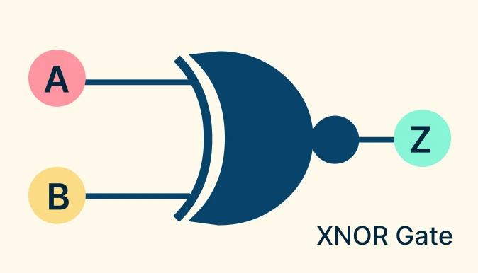
XNOR (Exclusive NOR) Gate
The XNOR gate is the opposite of XOR. It outputs 1 (true) only when the inputs are the same; if the inputs differ, the output is 0. Think of it like a “match detector” where the output is ON only when both inputs agree (both ON or both OFF).
XNOR Gate Symbol: Its symbol is the XOR gate symbol with a small circle (NOT bubble) at the output.
XNOR Gate Truth Table Boolean Equation: Y = A ⊙ B or Y = AB + A¯B¯ | ||
Input A | Input B | Output Y |
0 | 0 | 1 |
0 | 1 | 0 |
1 | 0 | 0 |
1 | 1 | 1 |
Real-world examples:
- Used in digital comparators to check equality between two binary values.
- Important in error detection and correction systems.
Elements of a Logic Gate Diagram
A logic gate diagram is a representation of how digital logic operations are structured and visualized. It can include several elements depending on the context.
Logic Gate Symbols
Logic gate symbols are standardized shapes used in circuit diagrams to represent different logic gates. Each gate symbol has a distinct shape with inputs entering from the left and the output leaving on the right. This method is the most common in electronic schematics and helps engineers and students easily visualize how signals flow through a circuit. Logic gate symbols follow established notations, such as ANSI/IEEE (American) and IEC (International) standards, which may vary slightly in shape but convey the same logic function.
Truth Tables
A truth table expresses a logic gate’s behavior in a tabular format, listing all possible input combinations along with their resulting outputs. Truth tables are especially useful for systematically analyzing and verifying logic operations, since they clearly show the complete functional behavior of a gate.
Boolean Algebra
Boolean expressions are a form of mathematical representation that is widely used to analyze, manipulate, and simplify digital logic. This allows designers to reduce complex circuits into more efficient forms using Boolean laws and algebraic techniques.
Circuit Connections
The wiring or pathways that link multiple gates together to form larger systems. These connections show how the output of one gate becomes the input to another, enabling more advanced operations such as adders, multiplexers, or even entire processors. Clear connections in a diagram help readers trace the signal flow step by step.
Input/Output Labels
Identifiers like A, B, C for inputs and X, Y, Z for outputs. Labels indicate where signals enter and leave the circuit, making it easier to map truth tables and Boolean expressions to the diagram. In larger systems, labels also prevent confusion when multiple signals cross or interact, ensuring that the circuit can be interpreted unambiguously.
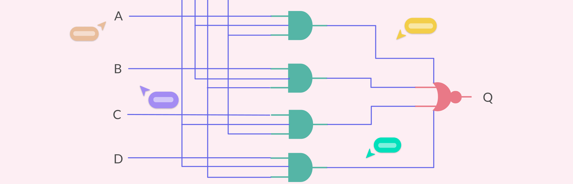
Combining Logic Gates to Build Integrated Circuits
Individual gates handle simple operations, but combining them creates integrated circuits (ICs) that power everything from calculators to computers. Modern ICs pack thousands or even millions of gates into a single chip, making them reusable building blocks for devices ranging from digital clocks to microprocessors.
When combined, logic gates can:
- Perform arithmetic operations: Addition, subtraction, multiplication, and division in CPUs are implemented using circuits built from XOR, AND, and OR gates (e.g., adders and multipliers).
- Store and process information: Flip-flops and latches, which are the foundation of memory, are created by combining NAND or NOR gates.
- Make decisions and comparisons: Comparators, multiplexers, and decoders are circuits formed by carefully arranged gates that evaluate inputs and choose outputs.
- Control system flow: Integrated circuits often use combinations of gates to enforce conditions, such as “run this process only if A and B are true, but not if C is active.
Why You Need a Diagramming Solution for Complex Circuits
As circuits grow in scale and complexity, logic gate diagrams become even more important for visualizing, designing, and troubleshooting how all the components work together. Manually sketching these connections quickly becomes overwhelming, especially when dealing with hundreds of gates and many different logic gate types. A dedicated diagramming solution helps by,
- Providing standard logic gate symbols: Ensures every gate is represented accurately and consistently.
- Reducing errors: Automated connectors and alignment tools prevent miswiring and confusion.
- Scaling easily: Makes it possible to design circuits with thousands of gates without clutter.
- Collaborating in real time: Teams can review, comment, and refine diagrams together.
- Exporting and reusing: Diagrams can be saved, shared, and embedded in technical documents or presentations.
With the right software, logic gate diagrams evolve from simple sketches into powerful blueprints for modern digital systems. Creately makes this process faster, clearer, and more collaborative with ready-made symbols, templates, and AI assistance.
Free Circuit Diagram Examples Using Logic Gates


FAQs about Logic Gate Types and Symbols
What are logic gates used for?
How are different logic gate types shown in diagrams?
Do logic gate symbols look the same everywhere?
Why are symbols better than just writing Boolean expressions?
What is the difference between basic and derived gates?
Why are NAND and NOR so important in circuit design?
Resources
Burch, Carl. “Logisim.” Journal on Educational Resources in Computing, vol. 2, no. 1, Mar. 2002, pp. 5–16, https://doi.org/10.1145/545197.545199.
Strong, J A. “Basic Gates.” Springer EBooks, 1 Jan. 1991, pp. 10–36, https://doi.org/10.1007/978-94-011-3118-6_2.