Understanding Piping and Instrumentation Diagram (P&ID) symbols is essential for anyone involved in process design, engineering, or plant operations. These standardized symbols form the visual language of process systems, allowing engineers to design, communicate, and maintain complex industrial setups accurately. In this guide, we’ll break down the different types of P and ID symbols, the international standards that define them, and the best practices to follow when creating or reading P&ID diagrams.
What are P&ID Symbols?
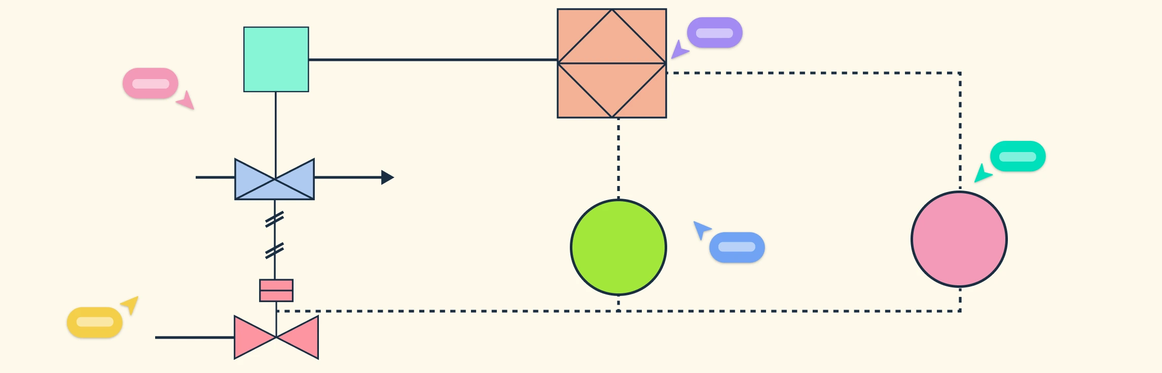
P&ID symbols are standardized graphical representations used to depict the various components and instruments on a piping and instrumentation diagram. These symbols visually convey how equipment, pipelines, valves, and control devices interact to form a complete process flow. Each symbol adheres to established engineering standards to ensure clear communication, consistency, and uniform understanding across design, construction, and maintenance stages.
Importance of P&ID Diagram Symbols in Engineering Design
Ensure consistency and clarity: Standardized symbols provide a common visual language that all engineers and technicians can interpret accurately, reducing confusion across teams.
Improve communication: They enable seamless collaboration between design, operations, and maintenance teams by representing complex systems in a universally understood format.
Enhance safety and compliance: Using correct symbols helps ensure that safety devices, control systems, and critical processes are properly identified, minimizing operational risks.
Support efficient troubleshooting: Clear representation of equipment and connections allows engineers to quickly locate faults and plan maintenance activities effectively.
Facilitate documentation and training: P&ID diagram symbols help create standardized documentation and serve as valuable references for training new personnel.
Align with industry standards: Adhering to recognized standards like ISA S5.1 or ISO 14617 ensures compliance and interoperability across global engineering projects.
Types of Piping and Instrumentation Diagram Symbols
P&ID symbols are organized into specific categories based on the equipment, components, and control devices they represent. Understanding each category is crucial for accurately interpreting process systems and ensuring clear communication across engineering teams.
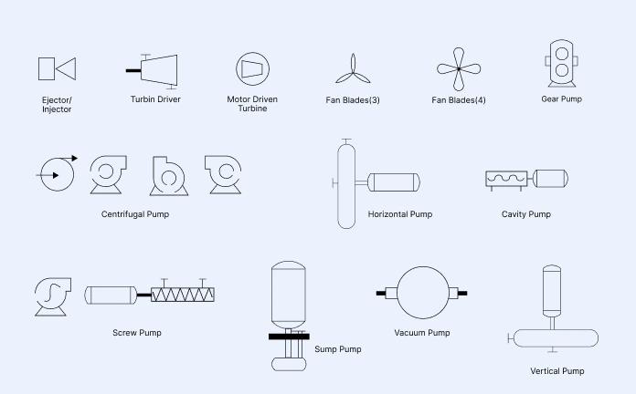
1. Pump Symbols
Pumps are essential components in process systems that move fluids by generating pressure or suction. They are represented using standard symbols for centrifugal, gear, cavity, vacuum, and vertical pumps, each illustrating the specific mechanism and flow direction involved in fluid transfer.
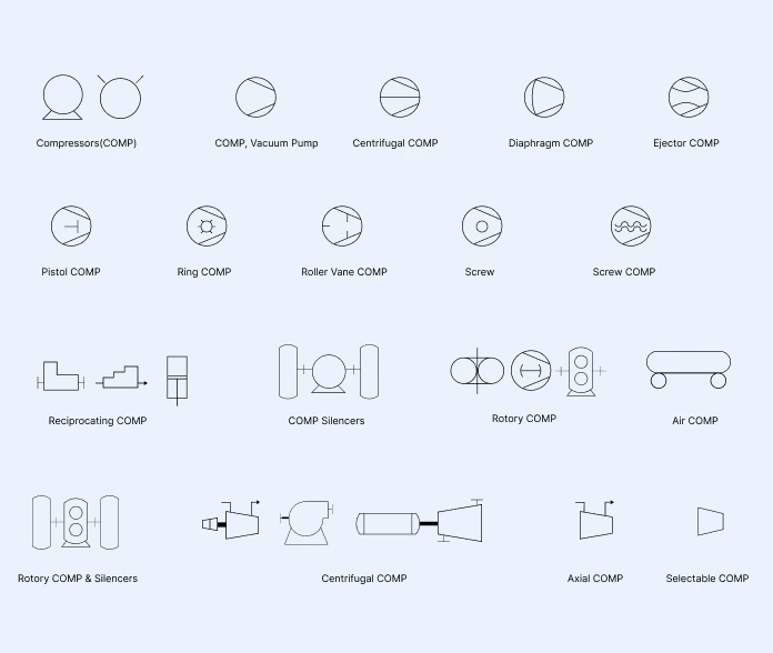
2. Compressor Symbols
Compressors increase gas pressure or reduce volume, with symbols distinguishing centrifugal, reciprocating, rotary, and axial types. These symbols ensure accurate representation of flow and mechanical function in process, gas, and HVAC systems.
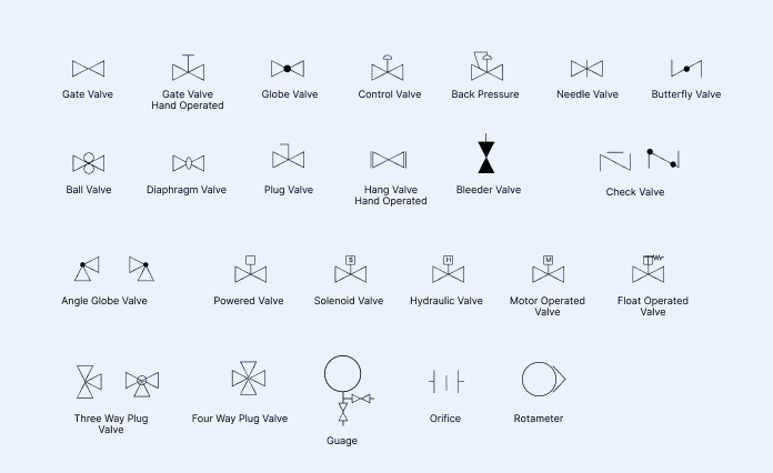
3. Valve Symbols
Valves regulate fluid flow by starting, stopping, or throttling movement through pipelines and may also relieve excess pressure. Common P&ID valve symbols include gate, globe, ball, butterfly, plug, check, and hydraulic valves with manual, electric, or pneumatic actuators, indicating their mode of operation.
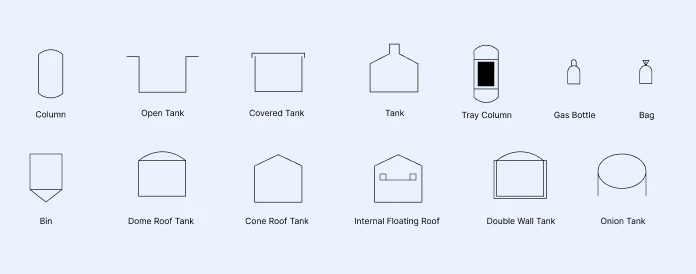
4. Vessel Symbols
Vessels represent containers that store or process liquids, gases, or slurries. Common vessel symbols include tanks, columns, bins and gas bottles. Their shape and labeling indicate orientation (horizontal or vertical) and function—whether it’s a mixing vessel, storage tank, or distillation column.
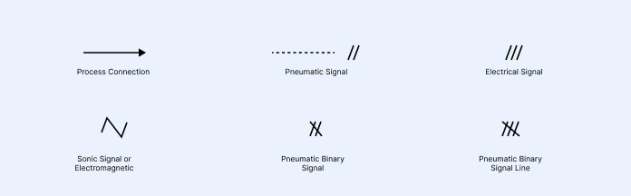
5. Instrumentation Signal P&ID Symbols
Instrumentation signal symbols represent the types of communication or transmission lines used between instruments and control devices. They indicate how signals are conveyed, such as electrical, pneumatic, or sonic, and help differentiate the method of data transfer and control within a process system.
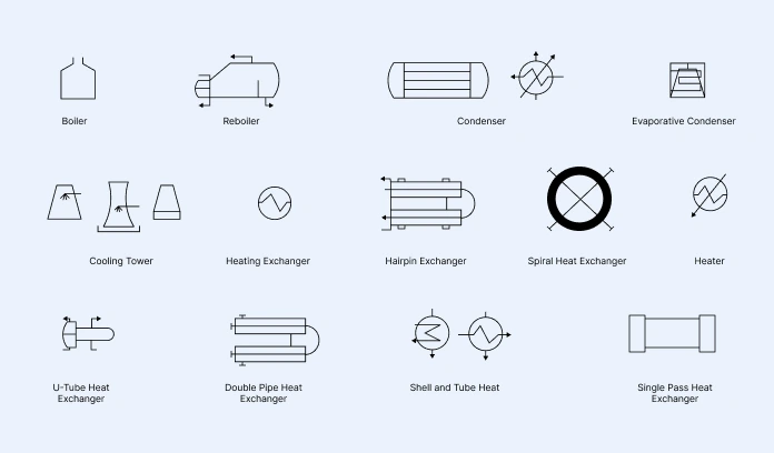
6. Heating Equipment Symbols
Heat exchangers transfer energy between two or more fluids without mixing them. Their symbols vary based on the design and application, such as hairpin, spiral, and double-pipe exchangers.
Check out how to read piping and instrumentation diagrams to learn how to interpret these P&ID diagram symbols, equipment tags, and abbreviation codes.
P&ID Symbol Standards and References
P&ID diagram symbols follow internationally recognized standards to maintain consistency, accuracy, and interoperability across engineering projects. These standards ensure that diagrams are easily understood by engineers, operators, and contractors worldwide, regardless of the software or industry they work in.
ISA S5.1 (Instrumentation Symbols and Identification): Established by the International Society of Automation (ISA), this is the most widely used standard for defining instrumentation and control symbols. It specifies how instruments should be identified, labeled, and connected within a P&ID, ensuring a consistent approach across all process industries.
ISO 14617 (Graphical Symbols for Diagrams): This international standard by the International Organization for Standardization defines general graphical symbols for use in technical diagrams, including mechanical, electrical, and process engineering. It promotes visual consistency across disciplines.
ANSI/ISA-5.3 (Graphic Symbols for Distributed Control/Shared Display Instrumentation, Logic, and Computer Systems): This American National Standards Institute standard extends ISA S5.1 to include symbols for modern control systems, such as programmable logic controllers (PLCs) and distributed control systems (DCS).
BS 5070 and DIN 28004: British and German standards that also define symbol conventions for process diagrams, often used regionally in Europe and referenced in international projects.
Following these standards helps maintain a universal visual language in process design, reduces miscommunication, and ensures compliance with regulatory and safety requirements. Creately’s P&ID diagram software comes with standard P and ID symbols, making it easy to design accurate and compliant diagrams.
Best Practices for Using Instrumentation Diagram Symbols
Follow standard conventions: Use standardized symbols from ISA S5.1, ISO 14617, or ANSI to maintain clarity and compatibility across teams and software platforms.
Label instruments accurately: Assign clear and consistent tag numbers, loop identifiers, and abbreviations (e.g., PT for Pressure Transmitter, TIC for Temperature Indicating Controller) so that every instrument can be easily traced in the system.
Maintain logical organization: Arrange instruments and equipment in a way that reflects actual process flow. Group related instruments near their respective equipment to make the diagram easier to interpret.
Avoid symbol overlap and clutter: Keep adequate spacing between lines, labels, and symbols to maintain readability. Use consistent line weights and connection styles to avoid confusion.
Verify connections and line types: Double-check that instruments are correctly connected to pipelines, controllers, and process units. Use appropriate line types (e.g., solid, dashed, or dotted) to differentiate between signal types — electrical, pneumatic, or hydraulic.
Include P&ID legends and references: Always provide a P&ID legend or reference table explaining the meaning of abbreviations, symbols, and tag identifiers. This P&ID symbols chart helps new users quickly understand the diagram.
Version control and documentation: Keep track of revisions with date and author annotations. Ensure updated versions are shared across all stakeholders to prevent errors during construction or operation.
By following these best practices, engineers can produce P&IDs that are not only technically accurate but also easy to read, maintain, and update throughout a project’s lifecycle.
How P&ID and PFD Symbols Work Together
P&IDs and PFDs both represent process systems but at different levels of detail. PFDs illustrate the overall flow between major equipment, while P&IDs show every pipe, valve, and instrument used for control and operation. Together, they provide a complete view from process design to maintenance. If you’re designing or analyzing process systems, explore Creately’s process flow diagram software to easily build accurate, compliant PFDs with ready-made templates and standard symbols.
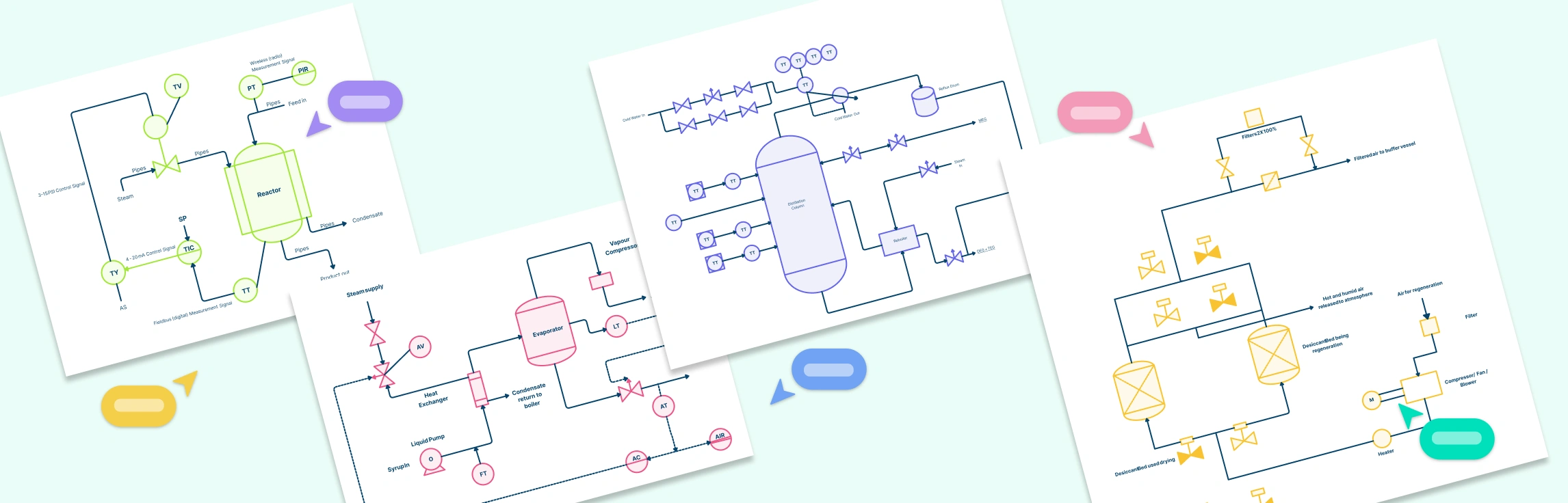
Free P&ID Diagram Templates to Get Started


FAQs about Piping and Instrumentation Diagram Symbols
How do I identify instruments in a P&ID?
Are P and ID symbols universal across industries?
What are common mistakes to avoid in P&IDs?
Resources
Chakrabarti, Sampa. “Basic Engineering.” Springer EBooks, 1 Jan. 2022, pp. 59–107, https://doi.org/10.1007/978-981-19-0660-2_3.
Elyan, Eyad, et al. “Symbols Classification in Engineering Drawings.” IEEE Xplore, 1 July 2018, https://ieeexplore.ieee.org/document/8489087.