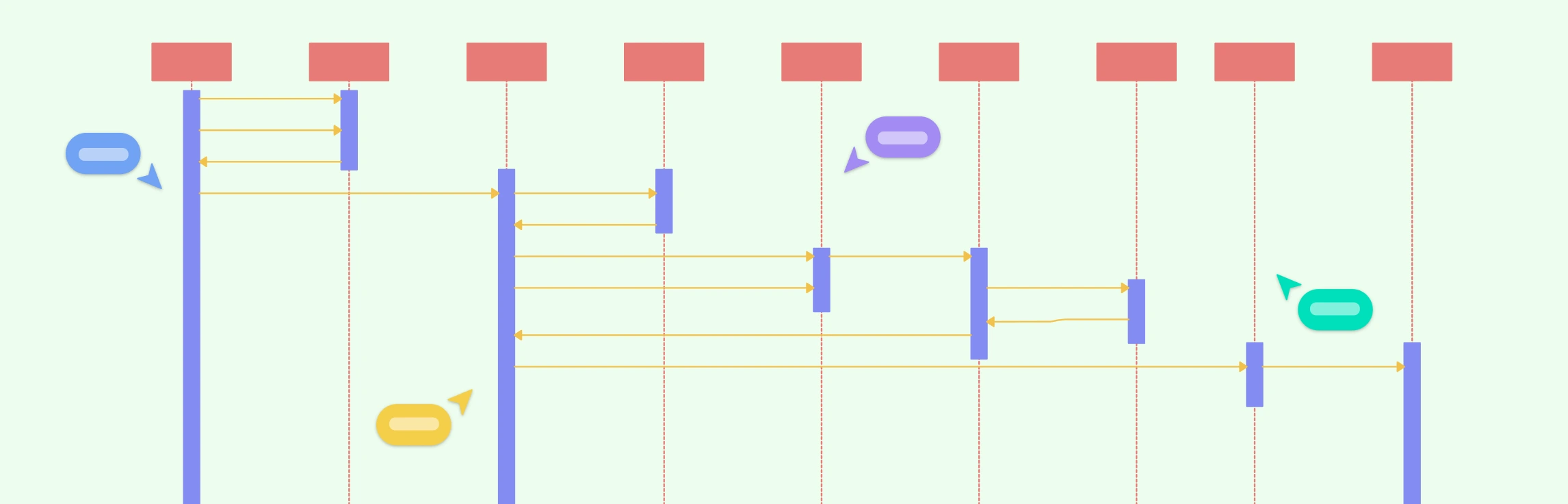
When designing a new system, tracking every interaction between components can be a nightmare. That’s why sequence diagrams are essential for illustrating how objects or components interact over time, making complex systems easier to understand for developers, analysts, and stakeholders alike. But with so many tools available, from intuitive drag-and-drop editors to text-based generators, choosing the right one can be overwhelming. In this guide, we break down the top sequence diagram tools, comparing their features, collaboration capabilities, templates, and export options, so you can pick the perfect tool for your workflow.
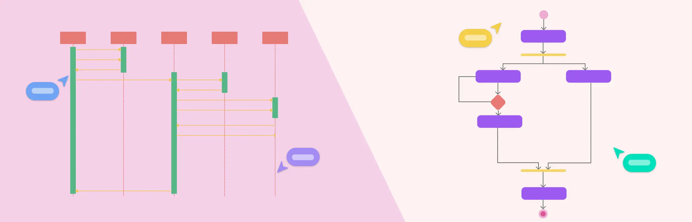
Visualizing how a system behaves is key to effective software design, and UML (Unified Modeling Language) makes this easy. Among its behavioral diagrams, the Sequence Diagram and Activity Diagram stand out for showing interactions and workflows. This guide explores Sequence vs Activity Diagram, highlighting their differences, components, and when to use each for clear, actionable system modeling.
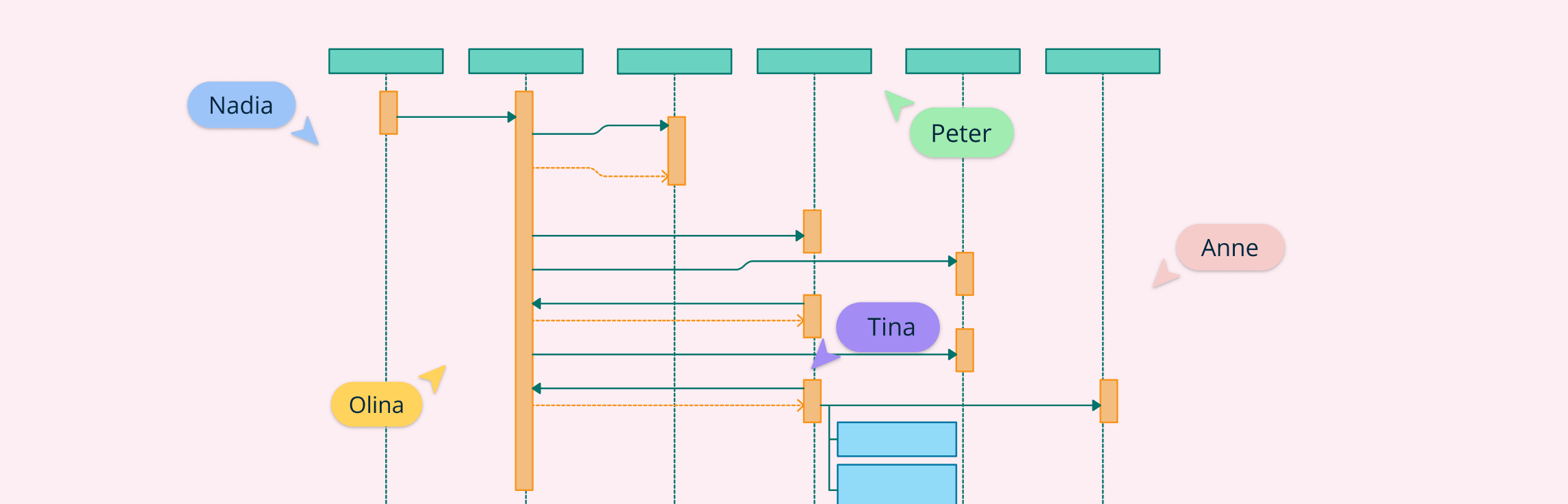
If you have trouble understanding what is a sequence diagram, this guide will provide everything you need to know, including the definition, notations, how to draw a sequence diagram, best practices, examples, and common mistakes you should avoid when drawing one.
A System Sequence Diagram (SSD) is a high-level UML sequence diagram that shows how external actors interact with the system as a single black box for a specific use case. It captures the time-ordered sequence of input events (messages) from actors to the system and the system’s observable responses, without revealing any internal objects, classes, or control flow. Let’s look at when to use UML system sequence diagrams, notations, a comparison with sequence diagrams and benefits.