When designing a database, one of the most important steps is understanding how information connects and flows. That’s where Entity-Relationship Diagrams (ERDs) come in. ERDs help us map out the key parts of a system—like people, products, or events—and how they relate to one another.
But did you know there are different types of ERD used at different stages of database design? In this guide, we’ll break down the types of entity relationship diagrams clearly and simply. You’ll learn what each type does, how they differ, and when to use them to create better, more organized database systems.
What Are the Types of ERD
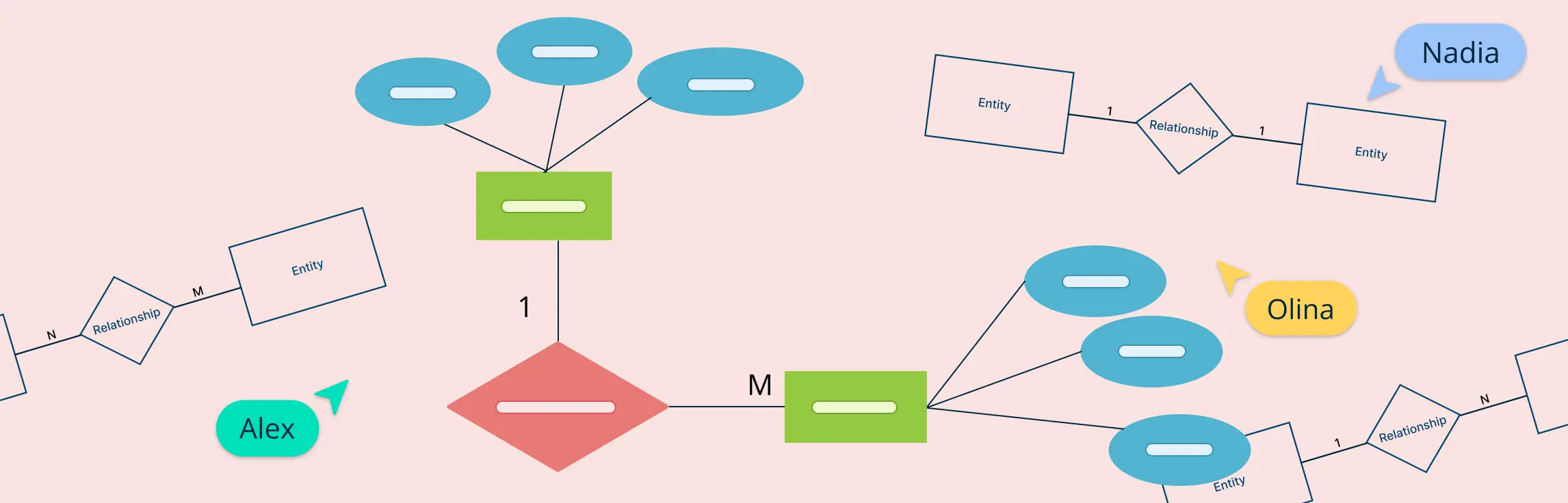
When designing a database, it’s not just about tables and fields. Before implementation, we need to carefully map out what data needs to be stored, how it’s connected, and how it should behave. That’s where entity-relationship diagrams come in. ERDs are a visual storytelling tool for databases, helping everyone from business stakeholders to developers align on structure and function.
There are three main ERD types, each serving a different purpose at different stages of the database design process:
- Conceptual ERD – Focuses on what the data is
- Logical ERD – Explores how the data is organized
- Physical ERD – Details how the data is stored in a specific system
Types of ERD at a Glance
| ERD Type | Focus | Level of Detail | Audience | Use Case |
| Conceptual | High-level entities & relationships | Abstract (no attributes or keys) | Business users, analysts | Brainstorming, scoping, stakeholder discussions |
| Logical | Attributes, keys, relationships | Detailed (normalized) | Analysts, designers | Data modeling, preparing for implementation |
| Physical | Tables, columns, data types, constraints | Very detailed (DBMS-specific) | Developers, DBAs | Implementation and performance optimization |
Let’s explore each type more deeply to understand how they help build smarter, more organized databases.
1. Conceptual ERD
At the start of any database project, it’s important to strip away complexity and focus on core concepts. A conceptual ERD does just that. Think of it as the blueprint for a building—it captures the overall structure, but without the technical or construction details.
Definition
It shows the main entities (the core objects or concepts, like “Customer” or “Order”) and the relationships between them (such as “places” or “contains”). However, it doesn’t go into specifics like data types or primary keys. It captures the overall structure of the system from a high-level business perspective.
Components
- Entities: These are the “nouns” of your system—the things you want to track. For a university system, entities might include Student, Professor, Course, and Department.
- Relationships: These are the connections between entities. For example, Student “enrolls in” Course, or Professor “teaches” Course.
Use cases
Conceptual ERDs are especially helpful during early discussions with stakeholders, project teams, or clients. They make it easier to talk about what the system needs to track—without getting lost in technical details. This stage is about clarity and shared understanding.
- Initial project scoping and discussions
- Aligning business users and technical teams
- Exploring domain concepts without getting technical
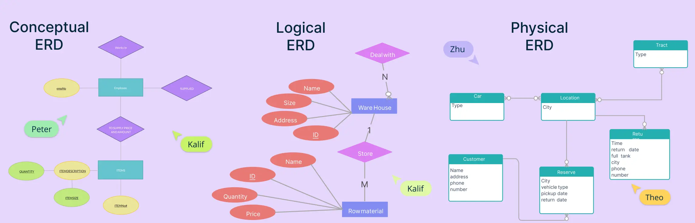
Example of a conceptual ERD
Conceptual ER Diagram


E-R Diagram for Supplies Contract System

2. Logical ERD
Once the big-picture idea is clear, it’s time to fill in the details. That’s where a logical ERD comes in. It refines the conceptual model by adding the building blocks of how the data should be organized.
Definition
A logical ERD adds attributes to entities (like name, email, or date of birth), defines primary keys (unique identifiers), and shows foreign keys (connections between entities). It also follows normalization rules to eliminate redundancy and ensure data integrity.
Components
- Attributes: Describe the details of each entity. For a Student, you might have student_id, first_name, email, and enrollment_date.
- Primary Keys (PKs): A unique value that identifies each record within an entity (e.g., student_id).
- Foreign Keys (FKs): Fields that establish links between entities (e.g., course_id in the Enrollment table pointing back to the Course entity).
- Normalization: Organizing data to minimize duplication and dependency—typically up to 3rd normal form (3NF).
Use cases
Logical ERDs are great for data modeling and analysis, helping teams plan a robust data structure without worrying yet about specific databases or software. They’re especially useful when choosing tools or preparing for implementation.
- Designing a platform-independent schema
- Analyzing data structure and relationships in detail
- Preparing for the next phase of physical implementation
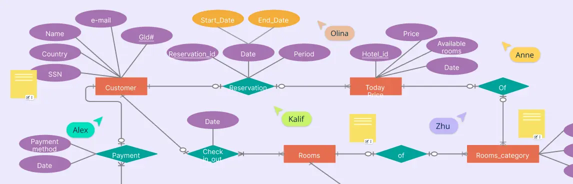
Example of logical ERD
Hospital Logical ERD

Factory ERD

3. Physical ERD
Now that the structure and relationships are fully defined, the final step is turning everything into a technical blueprint that can be implemented in a real database system. That’s what a physical ERD does.
Definition
A physical ERD is a detailed representation tailored to a specific database management system (DBMS), like MySQL, PostgreSQL, Oracle, or SQL Server. A physical ERD is platform-specific. It shows how the logical model translates into real tables, complete with column names, data types (like VARCHAR, INTEGER, or DATE), constraints (NOT NULL, UNIQUE), indexes, and more. This is the version your developers and DBAs will use to build the database.
Components
- Tables and Columns: Each entity becomes a table; each attribute becomes a column.
- Data Types: Specify the type of data a column stores (e.g.,
VARCHAR(100),DECIMAL(10,2)). - Constraints:
- Primary keys: Enforce uniqueness.
- Foreign keys: Maintain relational integrity.
- Default values, check constraints, and indexes: Ensure performance and validity.
Use cases
This ERD type is used during the database implementation phase. It ensures the design will run correctly and efficiently in the actual system. It’s especially important for developers and database administrators (DBAs) to maintain data integrity and performance.
- Database implementation and deployment
- Performance optimization and indexing
- Maintenance and updates by DBAs
Example of physical ERD
ER Diagram for Tracking Borrowing and Returning Activities
ER Diagram for System Integration with External Libraries

Conclusion: ERD Types
Understanding the types of ERD is the first step toward designing databases that are efficient, flexible, and easy to manage. Whether you’re planning a brand-new system or improving an existing one, using the right type of entity relationship diagram at the right stage makes a big difference.
By starting with a conceptual ERD, moving to a logical ERD, and finally creating a physical ERD, you ensure your database is well thought out from start to finish. Each of the ERD types builds on the last, giving you a clear, step-by-step path from an idea to a fully working system.
Taking the time to learn and apply these types will help you avoid mistakes, improve communication with your team, and build better databases that stand the test of time.
References
ResearchGate. (n.d.). (PDF) A Comparative Analysis of Entity-Relationship Diagrams. [online] Available at: https://www.researchgate.net/publication/243781001_A_Comparative_Analysis_of_Entity-Relationship_Diagrams.
Sciencedirect.com. (2016). entity relationship diagram - an overview | ScienceDirect Topics. [online] Available at: https://www.sciencedirect.com/topics/computer-science/entity-relationship-diagram.
Use a conceptual ERD at the very beginning of a project when you want to: It’s all about clarity before getting into technical details.FAQs on ERD Types
Why are there different types of ERD?
When should I use a conceptual ERD?
Which ERD type is best for beginners?
How detailed should each type of ERD be?
Is it okay to combine ERD types in one diagram?