Class diagrams are a fundamental part of UML notation, used to model the static structure of a system, including classes, interfaces, relationships, inheritance, and object interactions. Whether you’re a beginner or an experienced developer, having a UML Class Diagram Cheat Sheet ensures your diagrams are clear, consistent, and easy to understand.
This guide covers all essential UML guidelines and diagram rules for the below:
- General Guidelines
- Class Style
- Interfaces
- Relationship
- Inheritance
- Aggregation and Composition
What Is a Class Diagram?
A class diagram is one of the most widely used diagrams in the Unified Modeling Language (UML), serving as a blueprint for designing and understanding the structure of object-oriented systems. It visually represents the classes, attributes, operations (methods), and the relationships between them, offering a clear picture of how different parts of a system interact.


In essence, a class diagram describes the static structure of a system, what elements exist and how they are connected, rather than how they behave over time. Each class in the diagram acts as a template for creating objects in the program, defining their properties and the actions they can perform.
Try building one using an intuitive UML Class Diagram Tool,it lets you create, edit, and share class diagrams visually without needing to start from scratch.
Quick Reference Cheat Sheet Table
| Concept | Notation | Key Guidelines |
| Association | Solid line | Indicate multiplicity, center names, use active voice |
| Dependency | Dashed line | For transient relationships only |
| Inheritance | Solid line with closed arrowhead | Subclass below superclass, pure inheritance |
| Aggregation | Hollow diamond | Whole-part, conceptual relationships |
| Composition | Filled diamond | Whole-part, managed lifecycle, physical items |
| Interface Realization | Lollipop | Keep separate, do not copy attributes into classes |
1. General UML Class Diagram Guidelines
Class diagrams can serve multiple purposes, from communicating high-level requirements to detailing system designs. The UML class diagram guidelines below ensure your diagrams remain accurate and readable across different contexts.
Show visibility only on design models to avoid clutter in analysis diagrams.
Assess responsibilities on domain diagrams, focusing on meaningful logic rather than implementation details.
Highlight language-specific visibility with property strings on design diagrams.
Display types only when necessary: on design diagrams for implementation, or on analysis diagrams if the type is an actual requirement.
Follow language naming conventions (e.g., Java uses PascalCase for classes and camelCase for methods).
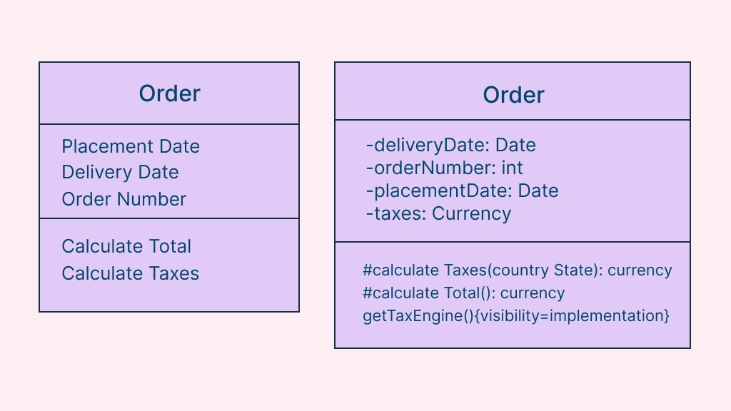
Fig.1: Analysis and Design Versions of a Class
Design class diagrams in UML should reflect language naming conventions. In the “Analysis and Design Version of a Class” image, you see that the design version of the Order class uses names that conform to common Java programming conventions, such as “placementDate” and “calculateTaxes()”.
- Model association classes in analysis diagrams: attach a dashed line to the association; treat the line, class, and dashed connector as one symbol.
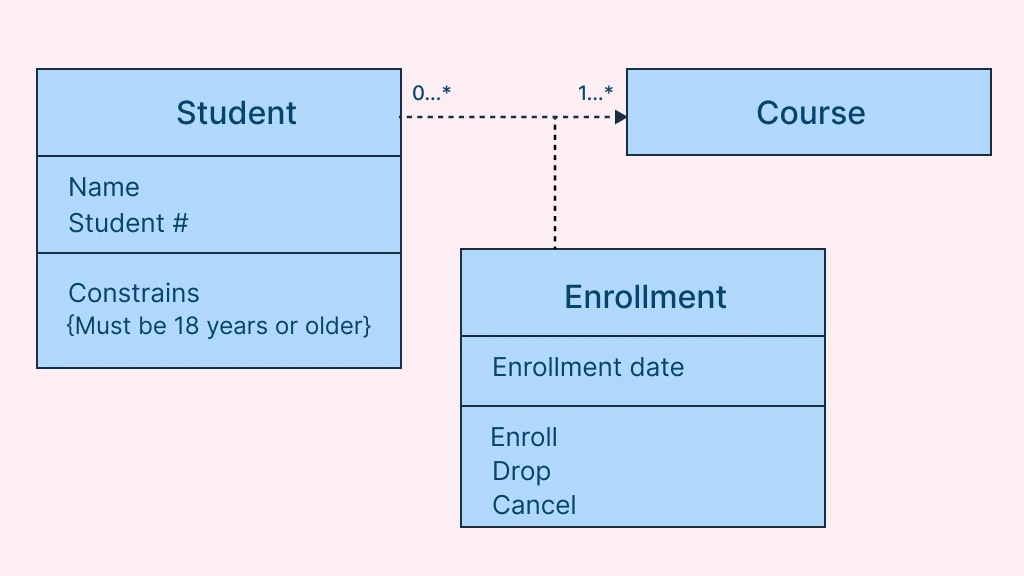 Fig.2: Modeling Association Classes
The image showing the “Modelling association classes” indicates the association classes that are depicted as a class attached via a dashed line to an association – the association line, the class, and the dashed line are considered one symbol in the UML.
- Do not name associations with association classes and ensure the dashed line is centered.
To get started, you can easily create your own diagrams using ready-made class diagram templates or customize one to fit your project’s structure.
2. Class Style Guidelines
A class is a template for objects, defining attributes (data) and operations (behavior). The following UML guidelines help maintain consistency and readability.
Naming Conventions
- Use common terminology to ensure clarity.
- Prefer singular, complete nouns for class names (e.g.,
OrderItem). - Name operations with strong verbs (
calculateTotal()). - Name attributes with domain-specific nouns (
shippingAddress).
Attributes & Operations
- Avoid modeling scaffolding code (boilerplate for relationships).
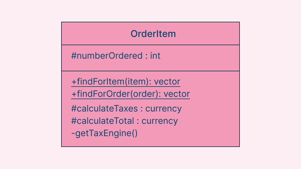 Fig.3: Class without Scaffolding
Scaffolding code refers to the attributes and operations required to use basic functionality within your classes, such as the code required to implement relationships with other classes. The image above depicts the difference between the OrderItem class without scaffolding code.
- Never show classes with only two compartments; label uncommon compartments clearly.
- Use an ellipsis (…) for incomplete lists.
- List static members first, followed by instance members.
- Order members by decreasing visibility.
- For object-type parameters, list only the type.
- Ensure consistent method signatures.
- Indicate exceptions in property strings (e.g.,
throws IOException). - Avoid stereotypes implied by programming language conventions.
3. Guidelines for Interfaces
An interface can be defined as a collection of operation signatures and/or attribute definitions that ideally define a cohesive set of behaviors. Interfaces are implemented, “realized” in UML parlance, by classes and components. In order to realize an interface, a class or component should use the operations and attributes that are defined by the interface. Any given class or component may use zero or more interfaces, and one or more classes or components can use the same interface.
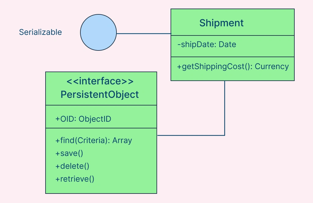 Fig.4: Interfaces on UML Class Diagrams
- Reflect implementation language constraints using the
<<interface>>stereotype. In the above image, you see that a standard class box has been used to define the interface PersistentObject (note the use of the<<interface>>stereotype). - Name interfaces following language naming conventions (e.g.,
PersistentObject). - Use “lollipop” notation to indicate interface realization.
- Define interfaces separately from classes.
- Do not include interface attributes or operations in implementing classes.
- Treat interfaces as a contract, defining required behavior without specifying implementation.
4. Relationship Guidelines
At this particular juncture, the term “relationships” will encompass all UML concepts such as aggregation, associations, dependencies, composition, realizations, and inheritance. In other words, if it’s a line on a UML class diagram, it can be considered a relationship. The following guidelines could be considered as “best practices,” and an effort should be made to adhere to them at all times.
- Model relationships horizontally for readability.
- Show collaboration only when there is a real dependency.
- Use dependencies for transient relationships in transition states.
- Combine similar relationships into a tree configuration to reduce clutter.
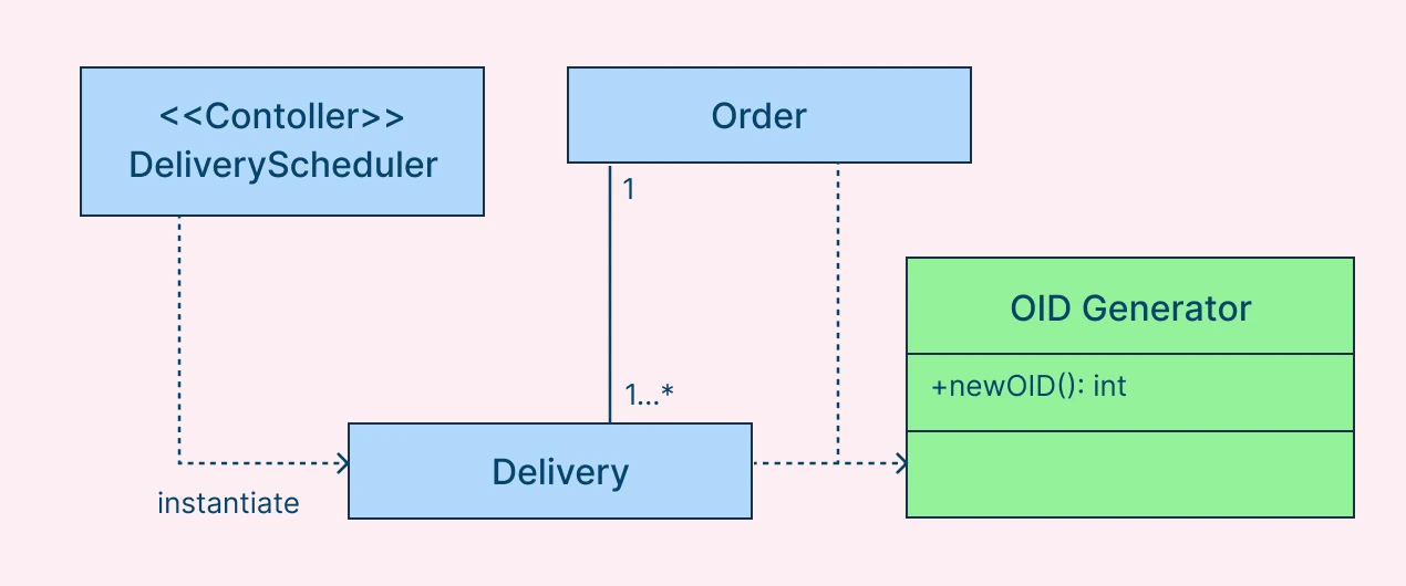 Fig.5: Dependency in Class Diagrams
In Fig.5, you see that both Delivery and Order have a dependency on OIDGenerator. Note how the two dependencies are drawn in combination in “tree configuration”, instead of as two separate lines, to reduce clutter in the diagram.
- Always indicate multiplicity, but avoid excessive use of
*. - Replace some relationships with attributes when appropriate (
customer.shippingAddress: Address).
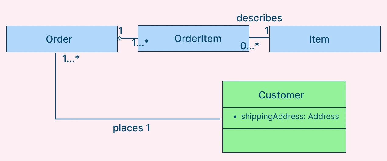 Fig.6: Association in Class Diagrams
In Fig.6, you see that the customer has a shippingAddress attribute of type Address, part of the scaffolding code to maintain the association between customer objects and address objects.
- Do not model implied relationships.
- Center association names and use concise, active voice.
- Indicate directionality; make associations bidirectional only when both classes collaborate.
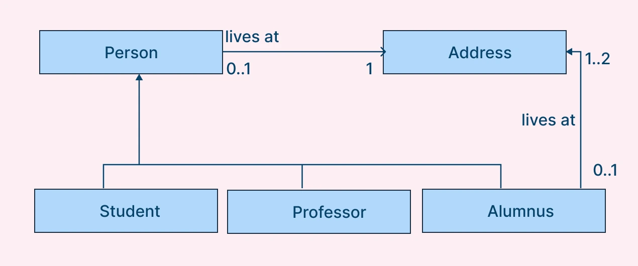 Fig.7: Unidirectional Relationship in Class Diagrams
The “lives at” association of Fig.7 is unidirectional.
- Include role names for multiple or recursive associations.
- Redraw inherited associations only if changes occur.
- Verify multiplicities (minimums and maximums) for correctness.
5. Inheritance Guidelines
Inheritance models “is a” and “is like” relationships, enabling you to conveniently reuse data and code that already exist. When “A” inherits from “B,” we say that “A” is the subclass of “B” and that “B” is the superclass of “A.” In addition to this, we have “pure inheritance” when “A” inherits all of the attributes and methods of “B”. The UML modeling notation for inheritance is usually depicted as a line that has a closed arrowhead, which points from the subclass right down to the superclass.
- Place subclasses below superclasses in diagrams.
- Use the closed-arrow notation pointing from subclass to superclass.
- Implement pure inheritance where the subclass inherits all attributes and operations.
- Apply the “plus in the sentence” rule for clarity.
- Consider data-based inheritance, ensuring logical alignment between subclass and superclass.
6. Aggregation and Composition Guidelines
As it is known, an object is made up of other objects. If you were to consider an example, it is similar to an airplane, which consists of wings, a fuselage, engines, flaps, landing gear, and so on. Another example would be a delivery shipment that contains one or more packages, or a team consisting of two or more employees. These are all examples of the concept of aggregation that illustrate “is part of” relationships. An engine is part of a plane, a package is part of a shipment, and an employee is part of a team.
Aggregation is a specialization of association, highlighting an entire-part relationship that exists between two objects. Composition is a much potent form of aggregation where the whole and parts have coincident lifetimes, and it is very common for the whole to manage the lifecycle of its parts. If you were to consider a stylistic point of view, aggregation and composition are both specializations of association, where the guidelines for associations do apply.
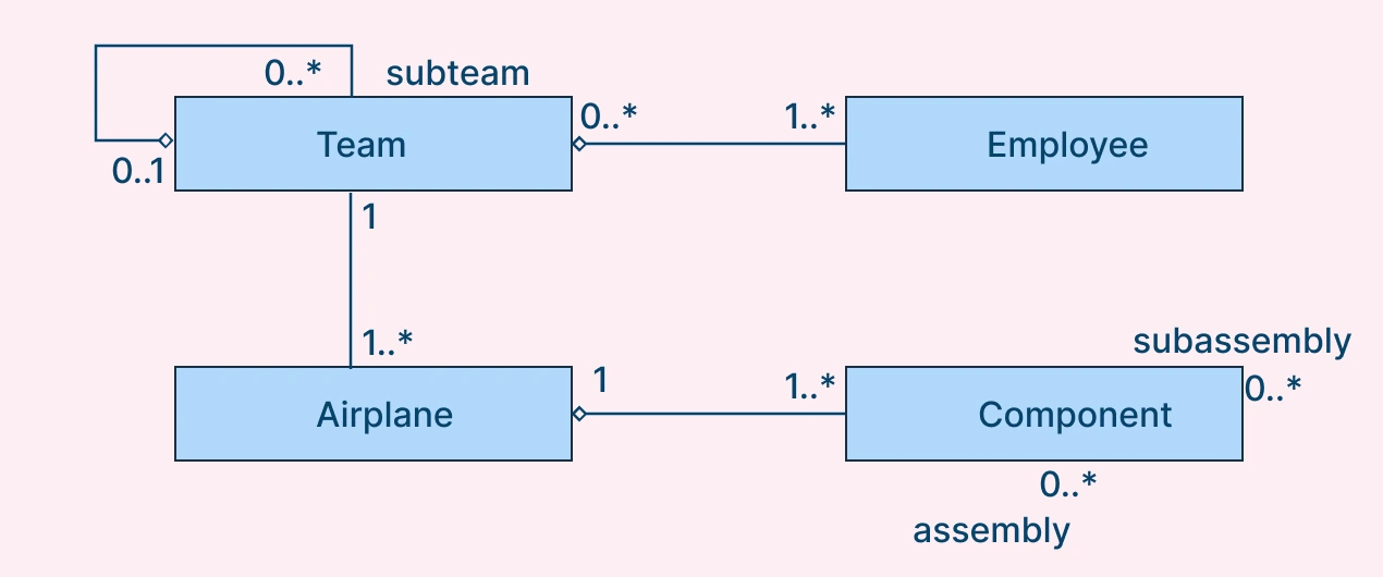 Fig.8: Aggregation and Composition in Class Diagrams
Aggregation
- Focus on both whole and part (e.g., a delivery shipment and its packages).
- Depict the whole on the left and part on the right.
- Use aggregation for conceptual relationships.
Composition
- Apply composition to physical or tightly coupled parts (e.g., engine in a plane).
- Use filled diamonds in UML notation.
- Follow association rules, as composition is a specialization of association.
This UML Class Diagram Cheat Sheet consolidates all essential UML guidelines and diagram rules for creating accurate, readable, and maintainable class diagrams. Following these UML Class Diagram rules ensures:
- Clear communication of system structure
- Consistency across diagrams
- Efficient modeling of object-oriented designs
Mastering UML class diagrams is easier when you understand the core guidelines and notation but the real value comes from putting that knowledge into practice. With an intuitive diagramming tool such as Creately, you can drag and drop classes, define relationships, and apply UML notation automatically, all on a collaborative visual canvas.
FAQs About UML Class Diagrams
What is the difference between a UML class diagram and an object diagram?
How do I use a UML cheat sheet effectively?
Can UML class diagrams be used in agile development?
Yes. UML class diagrams are valuable in agile development, but they are used lightweight and iteratively, rather than as heavy up-front documentation.
Teams often use them to:
- Communicate architecture quickly
- Clarify domain models with stakeholders
- Explain new or complex feature logic
- Support faster onboarding
In agile, the purpose is clarity, not completeness.