What is a UML Use Case Diagram
A UML (Unified Modeling Language) use case diagram is a visual representation of the interactions between actors (users or external systems) and a system under consideration. It depicts the functionality or behavior of a system from the user’s perspective. Use case diagrams capture the functional requirements of a system and help to identify how different actors interact with the system to achieve specific goals or tasks.
Importance of Use Case Diagrams
As mentioned before use case diagrams are used to gather a usage requirement of a system. Depending on your requirement you can use that data in different ways. Below are few ways to use them.
- To identify functions and how roles interact with them – The primary purpose of use case diagrams.
- For a high-level view of the system – Especially useful when presenting to managers or stakeholders. You can highlight the roles that interact with the system and the functionality provided by the system without going deep into inner workings of the system.
- To identify internal and external factors – This might sound simple but in large complex projects a system can be identified as an external role in another use case.
Use Case Diagram Components
Use case diagrams consist of 4 components.
- Actor
- Use case
- System
- Package
The components are further explained below.
| Symbol | Name | Description |
|---|---|---|
 | Actor | Actor in a use case diagram is any entity that performs a role in one given system. This could be a person, organization or an external system and usually drawn like skeleton shown below. |
 | Use Case | A use case represents a function or an action within the system. It’s drawn as an oval and named with the function. |
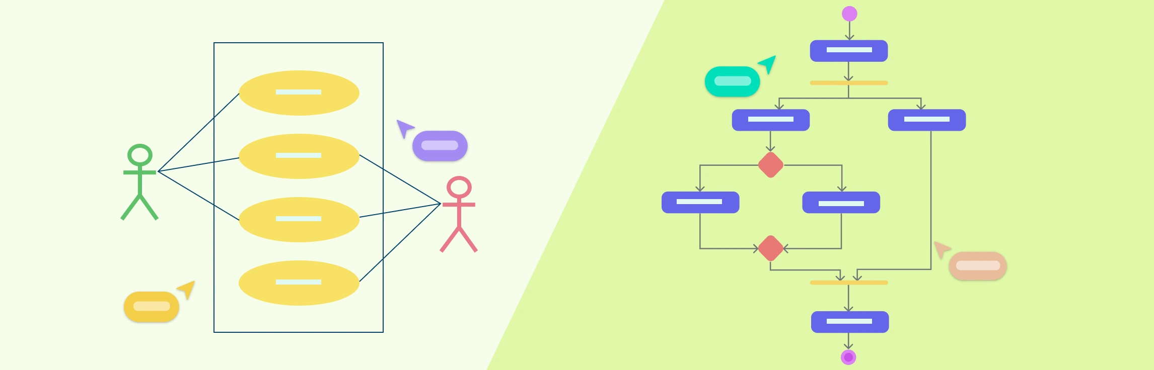
 | System | The system is used to define the scope of the use case and drawn as a rectangle. This an optional element but useful when you’re visualizing large systems. For example, you can create all the use cases and then use the system object to define the scope covered by your project. Or you can even use it to show the different areas covered in different releases. |
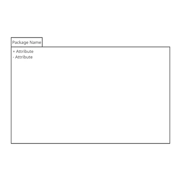 | Package | The package is another optional element that is extremely useful in complex diagrams. Similar to class diagrams, packages are used to group together use cases. They are drawn like the image shown below. |
Relationships in Use Case Diagrams
There are five types of relationships in a use case diagram. They are
Association between an actor and a use case
Generalization of an actor
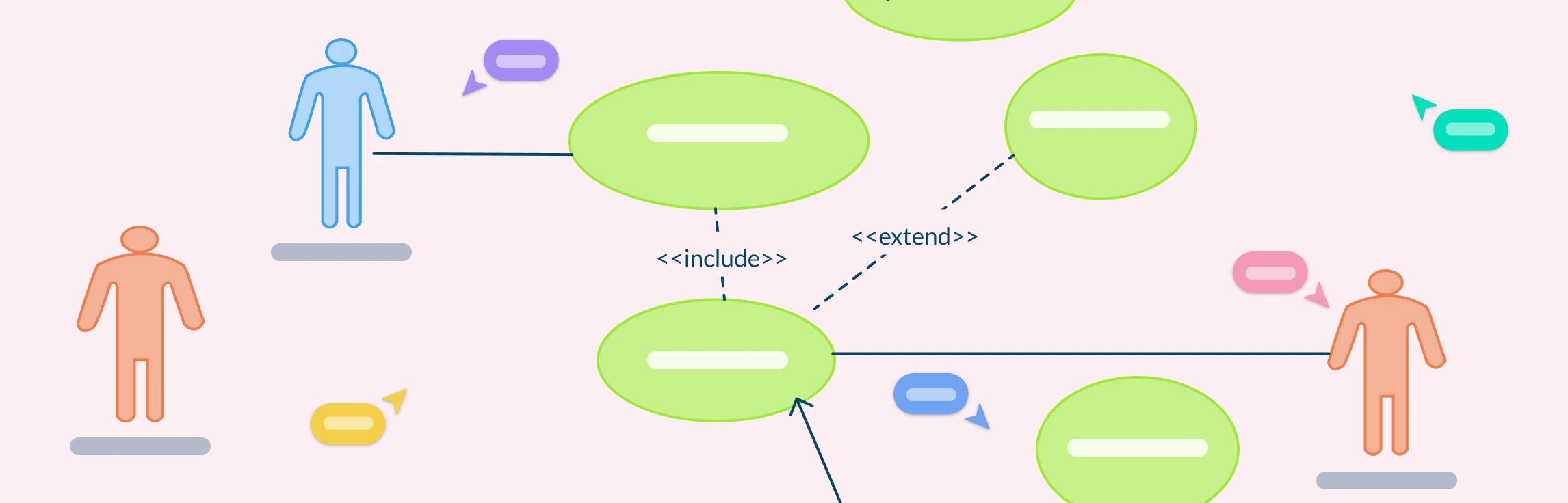
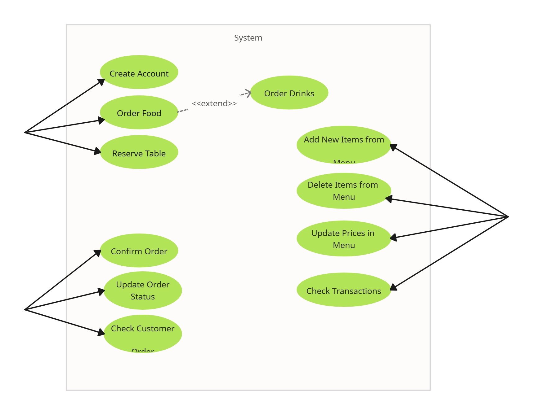
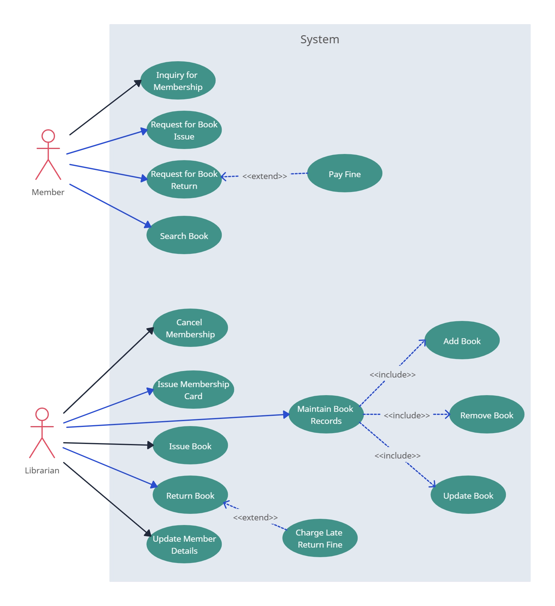
Extend relationship between two use cases
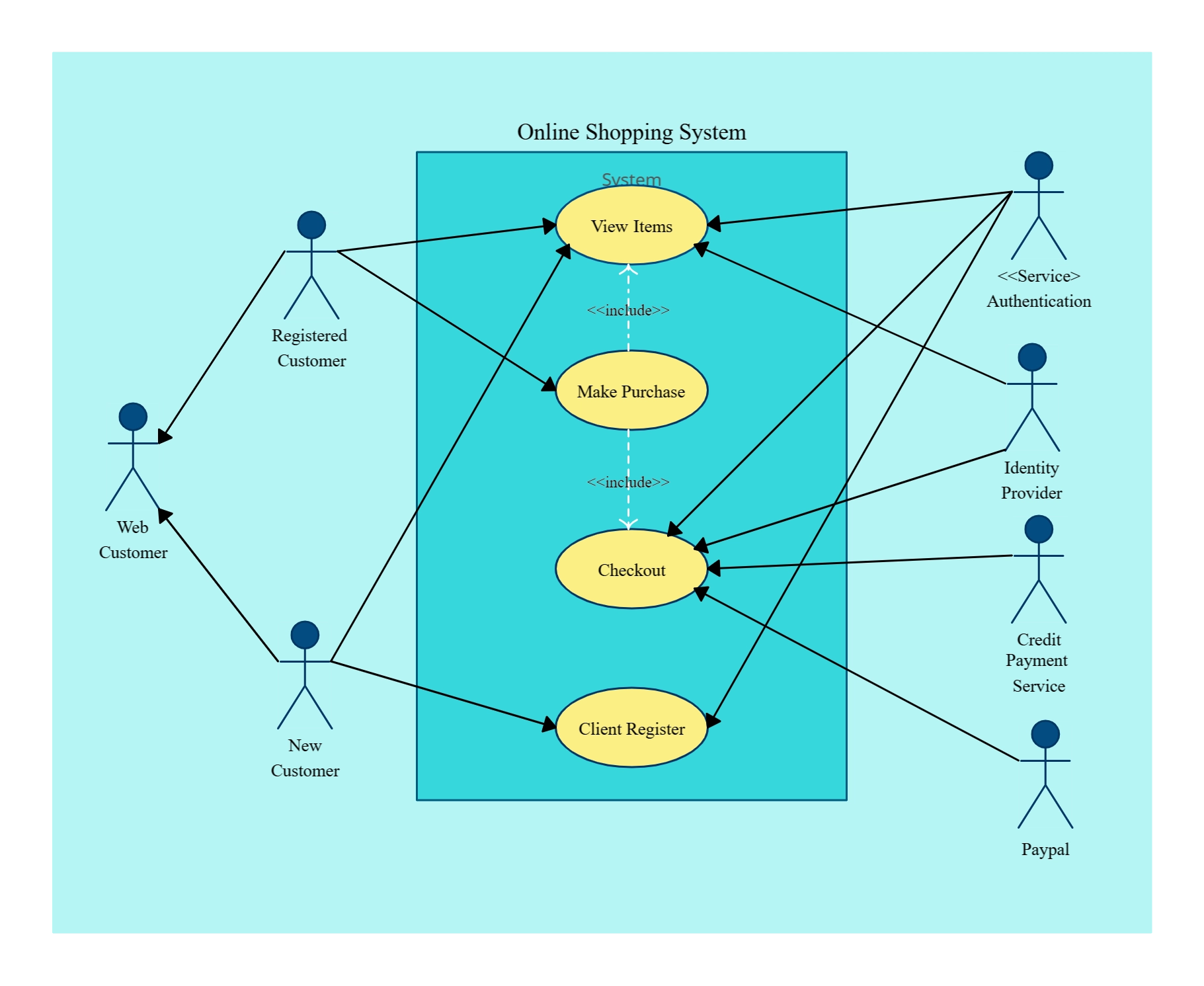
Include relationship between two use cases
Generalization of a use case
We have covered all these relationships in a separate blog post that has examples with images. We will not go into detail in this post but you can check out relationships in use case diagrams.
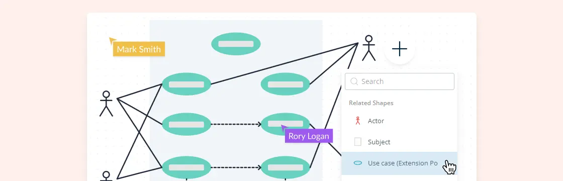
How to Make Use Case Diagram
Up to now, you’ve learned about objects, relationships and guidelines that are critical when drawing use case diagrams. I’ll explain the various processes using a banking system as an example.
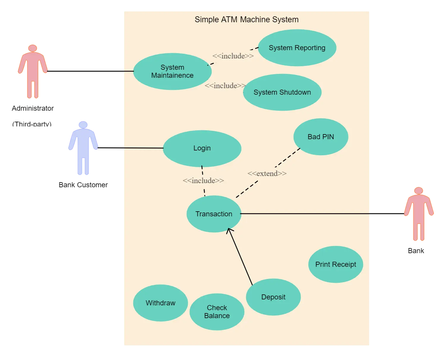
Identifying Actors
Actors are external entities that interact with your system. It can be a person, another system or an organization. In a banking system, the most obvious actor is the customer. Other actors can be bank employee or cashier depending on the role you’re trying to show in the use case.
An example of an external organization can be the tax authority or the central bank. The loan processor is a good example of an external system associated as an actor.
Identifying Use Cases
Now it’s time to identify the use cases. A good way to do this is to identify what the actors need from the system. In a banking system, a customer will need to open accounts, deposit and withdraw funds, request check books and similar functions. So all of these can be considered as use cases.
Top level use cases should always provide a complete function required by an actor. You can extend or include use cases depending on the complexity of the system.
Once you identify the actors and the top level use case you have a basic idea of the system. Now you can fine tune it and add extra layers of detail to it.
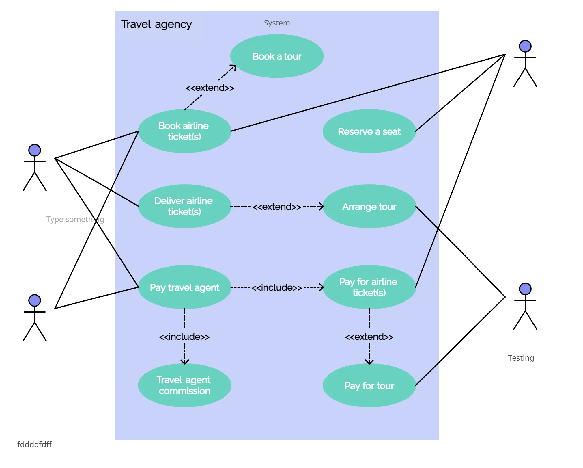
Look for Common Functionality to Use ‘Include’
Look for common functionality that can be reused across the system. If you find two or more use cases that share common functionality you can extract the common functions and add it to a separate use case. Then you can connect it via the include relationship to show that it’s always called when the original use case is executed. ( see the diagram for an example ).
Is it Possible to Generalize Actors and Use Cases
There may be instances where actors are associated with similar use cases while triggering a few use cases unique only to them. In such instances, you can generalize the actor to show the inheritance of functions. You can do a similar thing for use case as well.
One of the best examples of this is “Make Payment” use case in a payment system. You can further generalize it to “Pay by Credit Card”, “Pay by Cash”, “Pay by Check” etc. All of them have the attributes and the functionality of payment with special scenarios unique to them.
Optional Functions or Additional Functions
There are some functions that are triggered optionally. In such cases, you can use the extend relationship and attach an extension rule to it. In the below banking system example “Calculate Bonus” is optional and only triggers when a certain condition is matched.
Extend doesn’t always mean it’s optional. Sometimes the use case connected by extending can supplement the base use case. The thing to remember is that the base use case should be able to perform a function on its own even if the extending use case is not called.
Use Case Diagram Templates
Browse our full library of customizable use case templates.