Ever started designing a system only to realize your team is mixing up user flows with system structures? You’re not alone. UML diagrams are essential tools in software design and UML modeling, helping teams visualize how systems behave and how their components interact. Among the most commonly used types, use case diagrams and class diagrams are often confused, yet they serve entirely different purposes. While one focuses on system behavior and user interactions, the other captures the internal structure and relationships between classes. In this guide on use case diagram vs class diagram, we’ll break down their key differences, explore real-world use case diagram examples and class diagram examples, and share ready-to-use templates to help you create both effortlessly.
What Is a Use Case Diagram?
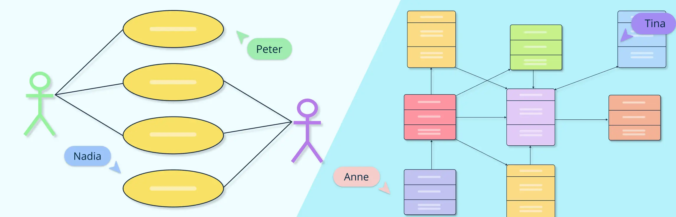
A use case diagram in UML is a visual representation that illustrates how users (actors) interact with a system to achieve specific goals. It focuses on the functional aspects of a system, what it does rather than how it’s built. In simple terms, a use case diagram shows the relationships between actors (like users or external systems) and the various use cases or functions they perform. This makes it an essential part of use case modeling, helping teams capture requirements and define system boundaries early in the development process. A use case diagram example typically includes elements such as users, system boundaries, and functional interactions, making it ideal for communicating features to stakeholders before diving into detailed design.


What Is a Class Diagram?
A class diagram in UML is a structural diagram used in object-oriented modeling to define the blueprint of a system. It represents the system’s classes, along with their attributes, methods, and the relationships between them, such as inheritance, association, and dependency. Unlike use case diagrams that focus on behavior, class diagrams emphasize the structure of a system, showing how different components interact internally. They play a vital role during the later stages of software design and development, helping developers translate conceptual models into actual code. A typical class diagram example might include classes like “Customer,” “Order,” and “Product,” each connected through defined relationships that form the foundation of the system’s architecture.

Use Case Diagram vs Class Diagram: Key Differences
To clearly understand the difference between a use case and a class diagram, it’s helpful to compare them side by side. This UML comparison highlights their unique purposes, elements, and applications within UML diagram types.
Use Case Diagram vs Class Diagram | ||
| Aspect | Use Case Diagram | Class Diagram |
| Purpose | Illustrates system functionality and how users interact with it | Represents the internal structure of the system, including classes and their relationships |
| Focus | Behavior, processes, and user goals | Data, attributes, methods, and object relationships |
| Primary Elements | Actors, use cases, system boundaries, associations | Classes, attributes, methods, associations, inheritance, aggregation, composition |
| Level of Detail | High-level overview of system interactions | Detailed representation of system architecture and object relationships |
| Stage in Software Development | Early stage: requirements gathering, stakeholder communication, analyzing system behavior | Later stage: system design, object-oriented modeling, coding guidance |
| Audience | Non-technical stakeholders, business analysts, product owners | Developers, architects, technical team members |
| Examples | Online Shopping: Place Order, Process Payment | Online Shopping: Customer, Order, Product, Payment classes and relationships |
| Benefits | Clarifies functional requirements, identifies actors and workflows, aids in requirement validation | Provides blueprint for implementation, defines data structures, ensures proper system architecture |
| Limitations | Does not show internal system structure or relationships between objects | Can be complex and harder to understand for non-technical stakeholders |
| Goal | Ensure system meets user needs and expected interactions | Ensure system is correctly structured and implementable based on requirements |
Both diagrams complement each other in the UML process: use case diagrams capture what the system should do from a user perspective, while class diagrams define how the system is structured to fulfill those requirements. Using them together ensures a smoother transition from conceptual modeling to detailed system design.
When to Use Each Diagram
In a typical UML workflow, the choice between a use case diagram and a class diagram depends on the stage of your project. You should start with a use case diagram when gathering user requirements or communicating with stakeholders. It helps visualize system functionality and ensures everyone understands the expected interactions before development begins.
Once the system’s functionality is defined, it’s time to transition to a class diagram. This diagram is essential during system design and implementation, as it maps out the structure of classes, their attributes, methods, and relationships. Using both diagrams in sequence ensures clarity in use case vs class diagram in software engineering, connecting user-focused requirements with the system’s internal architecture for a smooth development process.
Free Use Case Diagram and Class Diagram Templates
To make UML modeling easier, here are ready-to-use templates for both use case diagrams and class diagrams across common scenarios. Each example highlights how the two diagrams serve different purposes in the same system.
1. Bank ATM System
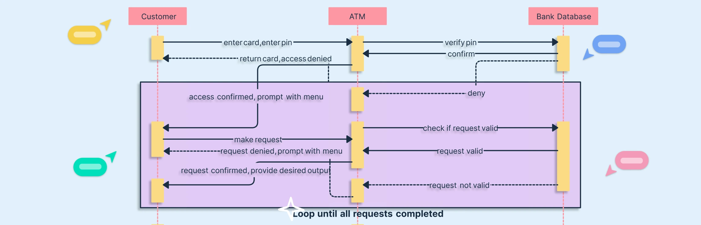
Use Case Diagram: Shows the interactions between users (like Customer and Bank Staff) and the ATM system. Typical use cases include Withdraw Cash, Deposit Money, Check Balance, and Transfer Funds. This diagram is ideal for capturing system functionality and stakeholder requirements.
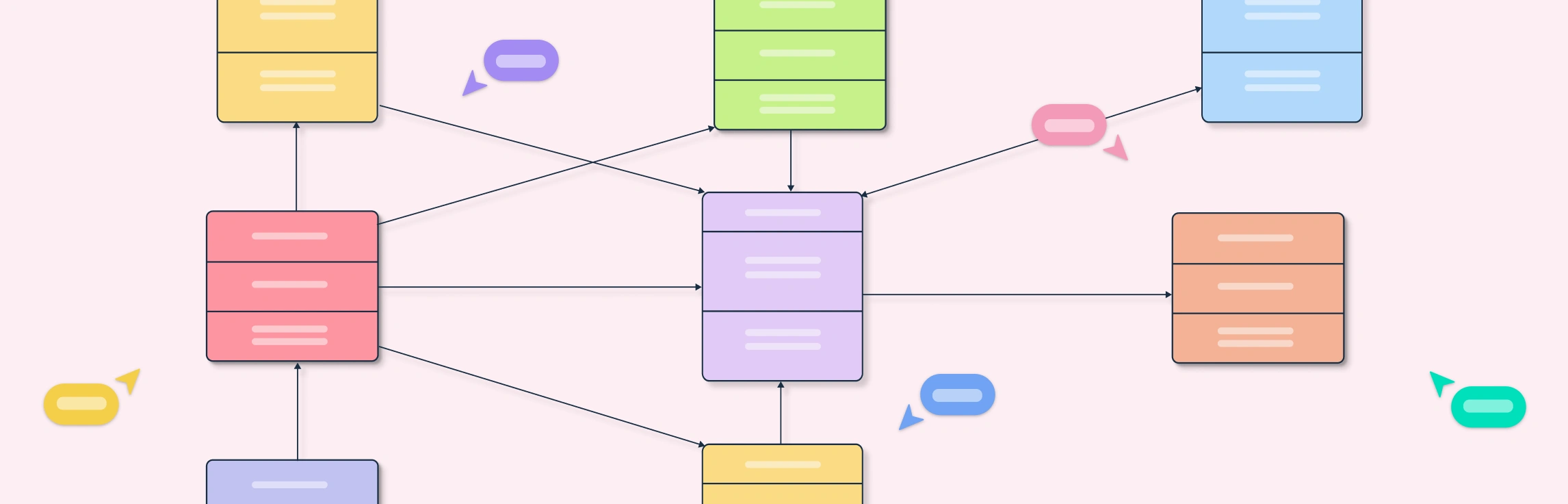
Class Diagram: Illustrates the system’s internal structure, including classes like
ATM,Account,Transaction, andBankCard. It shows attributes, methods, and relationships (e.g.,Accountassociated withTransaction). This diagram is used for object-oriented modeling and guides implementation.


Library Management System
Use Case Diagram: Focuses on interactions between actors like Members and Librarians and the system. Typical use cases include Issue Book, Return Book, Search Catalog, and Reserve Book. This diagram captures system functionality, user goals, and workflow, making it ideal for requirements gathering and stakeholder communication.
Class Diagram: Represents the internal structure of the library system with classes such as
Book,Member,Loan,Librarian, andCatalog. It shows attributes (e.g.,Book.title,Member.id), methods (e.g.,Loan.issueBook()), and relationships (e.g.,Memberassociated withLoan). This structural diagram guides developers during the system design and implementation phases.


Airline Reservation System
Use Case Diagram: Illustrates how actors like Passenger, Booking Agent, and Admin interact with the system. Common use cases include Book Flight, Cancel Booking, Check Flight Status, Manage Reservations, and Generate Ticket. This diagram helps capture system functionality and user interactions, making it ideal for requirements analysis and stakeholder discussions.
Class Diagram: Shows the system’s internal structure with classes such as
Flight,Passenger,Booking,Ticket, andPayment. It details attributes (e.g.,Flight.number,Passenger.name), methods (e.g.,Booking.confirm()), and relationships (e.g., aPassengercan have multipleBookings). This diagram is crucial during object-oriented modeling and system implementation.


Hospital Management System
Use Case Diagram: Highlights interactions between actors such as Doctor, Nurse, Patient, and Admin. Common use cases include Schedule Appointment, Update Patient Records, Prescribe Medication, Manage Billing, and Admit/Discharge Patient. This diagram is ideal for capturing system functionality and communicating requirements to stakeholders early in the UML workflow.
Class Diagram: Represents the internal architecture of the hospital system with classes like
Patient,Doctor,Appointment,MedicalRecord,Billing, andWard. It details attributes (e.g.,Patient.id,Doctor.specialization), methods (e.g.,Appointment.schedule()), and relationships (e.g.,Patientassociated withMedicalRecord). This structural view is essential during object-oriented modeling and system implementation.


Hotel Management System
Use Case Diagram: Shows how actors such as Guest, Receptionist, Housekeeping Staff, and Admin interact with the system. Common use cases include Book Room, Check-In/Check-Out, Manage Reservations, Process Payments, and Request Room Service. This diagram helps define system functionality and user interactions, making it ideal for requirements gathering and stakeholder communication.
Class Diagram: Represents the system’s internal structure with classes like
Guest,Reservation,Room,Payment, andServiceRequest. It details attributes (e.g.,Room.number,Guest.name), methods (e.g.,Reservation.confirmBooking()), and relationships (e.g., aGuestcan have multipleReservations). This structural diagram is key for object-oriented modeling and guiding development.


Why Use Creately for UML Diagramming
Creately is a powerful UML diagram software that simplifies the creation of both use case diagrams and class diagrams. Its intuitive interface and robust features make it an ideal UML design tool for teams of all sizes. Here’s why Creately stands out:
- Drag-and-Drop Feature: Easily add and connect UML shapes without complex formatting.
- Comprehensive UML Shape Library: Access all standard UML symbols for diagrams like use case, class, sequence, and more.
- Real-Time Collaboration: Work with your team simultaneously, making updates visible instantly.
- Pre-Built UML Template Library: Start quickly with ready-made templates for various UML diagram types.
- Export and Sharing Options: Export diagrams in multiple formats and share with stakeholders seamlessly.
- Infinite Canvas: Design large, complex diagrams without running out of space.
- Integrations: Connect with Jira, GitHub, and Confluence to streamline your development workflow.
With these features, Creately makes collaborative UML diagrams effortless, allowing teams to visualize system functionality and structure clearly while saving time and improving accuracy in UML modeling. Whether you’re creating use case diagrams, class diagrams, or other UML diagram types, Creately provides the tools and flexibility to simplify the entire design process.
In the use case diagram vs class diagram comparison, use case diagrams focus on system functionality and user interactions, making them ideal for early-stage requirements gathering, while class diagrams capture the system’s internal structure, guiding detailed design and implementation. Both diagrams play complementary roles in the software design process, ensuring that teams understand what the system should do and how it is structured. By using them together, you can streamline development, reduce misunderstandings, and improve system quality. Try Creately’s UML templates to visualize your next project effortlessly and experience how easy it is to create professional, collaborative UML diagrams.