A System Sequence Diagram (SSD) is a high-level UML sequence diagram that shows how external actors interact with the system as a single black box for a specific use case. It captures the time-ordered sequence of input events (messages) from actors to the system and the system’s observable responses, without revealing any internal objects, classes, or control flow. Let’s look at when to use UML system sequence diagrams, notations, a comparison with sequence diagrams and benefits.
When to Use UML System Sequence Diagrams
During Early Requirements Analysis: Use SSDs at the beginning of system design to capture how external actors (users or other systems) interact with the system as a single black box. They help analysts and stakeholders agree on what the system should do before internal details are designed.
To Model System Behavior for a Use Case: Create an SSD to represent the input and output events for a particular use case (e.g., Borrow Book, Login User, Submit Payment). It shows how the system reacts to each external event.
To Define System Operations and Responsibilities: SSDs help identify the system operations (e.g., validateUser(), processOrder(), generateInvoice()) that the system must perform in response to actor inputs. These become the basis for defining methods in the system’s interface.
When Defining System Boundaries: Use SSDs to distinguish between what the system handles internally and what happens in the external environment, making boundaries and interactions explicit.
To Validate Use Case Scenarios with Stakeholders: SSDs simplify communication by showing the sequence of messages exchanged between the actor and the system in a single diagram. They allow non-technical stakeholders to validate that the described behavior matches their expectations.
When Preparing for Interface Design or API Mapping: SSDs serve as a blueprint for defining system interfaces or service endpoints by listing all possible system-level messages and responses involved in a use case.
For Deriving Contracts and Test Cases: SSDs help define system operation contracts and are valuable for designing functional test cases that verify correct responses for each external event.
System Sequence Diagram Notations
A UML System Sequence Diagram models the interaction between external actors and the system for a specific use case. It focuses on what messages are exchanged, not how the system processes them internally.
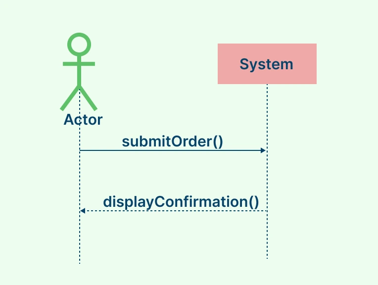
Actors: Represent external users or systems interacting with the main system. Shown as stick figures on the left side of the diagram.
System (System Box): Depicted as a large rectangle labeled “System” or with the system’s name. It serves as the single lifeline that represents the system as a black box.
Lifelines: Shown as vertical dashed lines which extend downward from both the actor and the system box. They represent the existence of each participant during the interaction.
Messages / Events: Horizontal arrows which show communication between the actor and the system.
Solid arrows → represent requests or actions sent by the actor to the system (e.g., submitOrder()).
Dashed arrows → represent responses or return messages from the system (e.g., displayConfirmation())
With Creately’s Sequence Diagram Tool, you can easily map these interactions, define message flows, and refine your system design.
System Sequence Diagrams Vs. Sequence Diagrams in UML
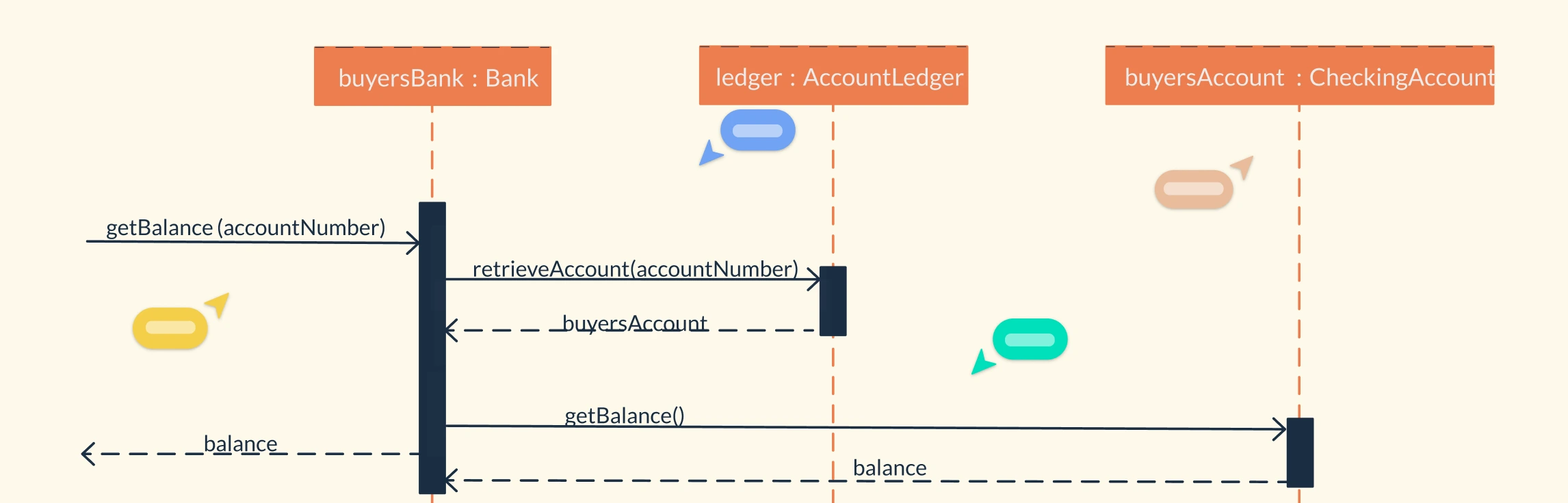
Both Standard Sequence Diagrams and System Sequence Diagrams (SSDs) are used to visualize how interactions occur in a system, but they serve different purposes and levels of detail. A standard sequence diagram focuses on internal object interactions, while a system sequence diagram provides a high-level view of how external actors communicate with the system as a single unit.
Aspect | Standard Sequence Diagram | System Sequence Diagram (SSD) |
Purpose | Models detailed object-level interactions within the system to show how components collaborate. | Models high-level interactions between external actors and the system as a black box. |
Focus | Emphasizes how the system works internally, showing message flow and logic between objects. | Emphasizes what the system does, showing input and output events between users and the system. |
Level of Detail | Detailed and represents method calls, object lifelines, and control flow. | Abstract and hides internal details, showing only external messages. |
Participants (Lifelines) | Multiple lifelines representing objects, classes, or components inside the system. | Usually two lifelines: external actors and a single system lifeline. |
Usage Stage | Used during system design and implementation to model internal behavior. | Used during requirements analysis to identify system responsibilities and interactions. |
Example | Shows how Customer, Order, and Inventory objects interact to process a purchase. | Shows a Customer sending placeOrder() to the System, and the system responding with orderConfirmation(). |
Benefits of a System Sequence Diagram
Clarifies System Behavior: Helps visualize how the system responds to external inputs, making it easier to understand its functional behavior for each use case.
Defines System Boundaries: Clearly separates what happens inside the system from what occurs outside, helping teams identify responsibilities between the system and external actors.
Improves Communication: Provides a simple visual representation that both technical and non-technical stakeholders can understand, promoting better collaboration.
Supports Requirements Analysis: Serves as a bridge between use case descriptions and design models, ensuring that all user interactions are captured and validated early in development.
Identifies Key Inputs and Outputs: Makes it easy to list the main events (messages) sent to and from the system, helping define system interfaces and API operations.
Facilitates System Design and Testing: Provides a foundation for defining system operations, test cases, and integration scenarios, ensuring completeness and consistency.
Enhances Documentation and Traceability: Acts as visual documentation that supports maintenance, change management, and future system updates.
Free UML System Sequence Diagram Templates to Get Started


FAQs about UML System Sequence Diagrams
Do System Sequence Diagrams include internal objects or logic?
Can a UML System Sequence Diagram include multiple actors?
Can the system request input from an actor?
Can a System Sequence Diagram include multiple systems or subsystems?
Resources
Campean, Felician, and Unal Yildirim. “Enhanced Sequence Diagram for Function Modelling of Complex Systems.” Procedia CIRP, vol. 60, 2017, pp. 273–278, https://doi.org/10.1016/j.procir.2017.01.053.
Kunii, Hideko S, et al. Conceptual Modeling - ER 2001. Springer, 30 June 2003.